AutoCAD TRIM Command
TRIM Command Access
COMMAND LINE: TRIM

DEFAULT KEYBOARD SHORTCUT: TR
RIBBON: HOME | MODIFY TAB | TRIM

How To Use The TRIM Command in AutoCAD
The TRIM command in AutoCAD is used to trim lines, polylines, circles, and arcs using another line, polyline, circle, or arc at the cutting edge.
The TRIM and EXTEND commands are in the same pull-down menu in the Modify tab, perform nearly the opposite actions of each other, and are so closely related that when one of the commands is active, pressing the SHIFT key morphs the active command into the other.
When the TRIM command is initiated, the first expected input is either the Cutting Edge. If no cutting edges are selected, and the ENTER key is pressed again ENTER is pressed twice in a row, one time to initiate the command, then a second time, every line, Pline, circle, arc, and ellipse becomes a cutting edge.
Pictured below is what the Dynamic Input looks like when the TRIM command is initiated.

The TRIM command has two selection modes and switching between them occurs immediately after initiating the command by entering ‘O’ at Dynamic Interface command line. Quick Selection or Standard Selection modes can either be picked with the mouse or by entering Q for Quick Selection or S for Standard Selection respectively. AutoCAD remembers the last selection mode chosen and that will be your default mode until the other is chosen.

Standard Selection mode is selected in the picture above for the TRIM command.
The selection mode refers to how the objects that are to be trimmed will be selected. In Standard selection mode, TRIM uses object selection methods described on the Three Methods to Select AutoCAD Objects page; direct, window, and crossing.
If the Quick selection method is selected, then every object becomes a cutting edge. To TRIM objects in the drawing, either directly select each object or hold down the left mouse button and drag the mouse around to cross every object you wish to TRIM. There is no limitation on the shape drawn that will select the objects to be cut or trimmed.
In the image below, the TRIM command is initiated in Quick Select mode. Note the shape of the white trimming line. It is an irregular shape and every drawing object that it crosses is trimmed.

TRIM Command Options:
1. cuTting edges
Enter T to select the cutting edge or cutting edges. If cutting edges have already been selected, and you wish to select a new set of cutting edges, enter T at the Dynamic Input and new cutting edges can be selected.
2. Fence
In the image below, a single dashed straight line is the Fence. Any object the Fence crosses will be trimmed.

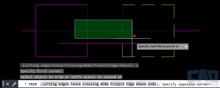
3. Crossing
Using the Crossing option will initiate the selection window to be a Crossing Window, regardless of the first direction the mouse is moved after the initial mouse click. Typically, when the mouse is moved to the right after the initial mouse click, a Window is created with the first direction the mouse moves is to the right. The Crossing option overrides that and allows the first mouse movement to the right to be a Crossing and not a Window.
4. mOde
Using the Mode option enables the user to switch between Quick and Standard selection modes while the command is active. The Mode option can be selected before drawing objects are selected and can also be selected while the command is active.

5. Project
The Project option allows the projection mode to be changed.
- None: Only objects that intersect with defined cutting edges are trimmed
- UCS: Only objects on the current XY plane of the UCS will be trimmed
- View: Only objects on the current view are cutting edges.

6. eRase
The Erase option allows objects to be erased while the TRIM command is active. This works very much like the standard ERASE command, and can be invoked while also using the TRIM command.

Frequently Asked Questions (FAQ)
TRIM removes unwanted portions of objects by cutting them back to selected boundaries. It is commonly used to clean up intersections, overlaps, and excess geometry without redrawing objects.
Not always. Modern versions of AutoCAD support implied boundaries, allowing you to select objects directly and let AutoCAD infer the cutting edges automatically.
Quick Trim allows you to click directly on objects to remove excess portions without explicitly selecting boundaries. Classic mode requires selecting boundaries first, then choosing what to trim.
TRIM may fail if objects do not intersect logically, are on locked layers, or if gaps exist between geometry. Zooming in often reveals small alignment issues.
Yes. TRIM works on lines, arcs, polylines, circles, and many other object types, making it ideal for cleaning complex drawings efficiently.
Yes. TRIM permanently modifies geometry by removing part of the object. If you need to preserve the original length, consider copying the object first.
Almost always. TRIM preserves alignment, reduces redraw errors, and significantly speeds up drawing cleanup compared to deleting and recreating objects.
Yes. TRIM supports window, crossing, and fence selections, allowing you to trim many objects in a single operation.
Ways to Use Trim
Learn advanced TRIM techniques using boundaries, SHIFT-extend, Window/Crossing, Lasso, and Fence selections. A complete guide to trimming faster and with more control.
Learn the most practical real-world uses of the AutoCAD TRIM command, including cleanup workflows, efficiency tips, and common drafting scenarios.

Learn the most common AutoCAD TRIM mistakes and how professionals avoid them. Fix failed trims, intersections, layers, and selection issues fast.
All Commands
Command Categories

Create
Explore all AutoCAD Create commands in one place. Learn how to use LINE, CIRCLE, ARC, POLYLINE, BLOCK, HATCH, and more with tutorials and practical examples.

Modify
Your complete guide to AutoCAD Modify tools—ERASE, TRIM, EXTEND, MOVE, ROTATE, OFFSET, FILLET, and more—with tips and workflows.

Notation
Complete guide to annotation in AutoCAD: text, dimensions, leaders, tables, zoom/pan basics, and clipboard tools.

Drafting Aids
Learn AutoCAD’s Drafting Aids and Precision Controls—OSNAP, Ortho Mode, Polar Tracking, Object Snap Tracking, and Dynamic Input. Improve accuracy, speed, and control with this complete guide.

All Commands
Browse every AutoCAD command in one place with this complete A–Z index. Quickly find command pages for LINE, ERASE, ZOOM, and more, with clear explanations and tips for efficient drafting.
Modify Commands