AutoCAD HATCH Command
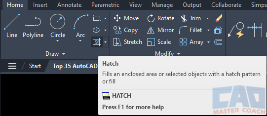
HATCH Command Access
COMMAND LINE: HATCH

DEFAULT KEYBOARD SHORTCUT: H or BH
RIBBON: HOME | DRAW TAB | HATCH
AutoCAD HATCH
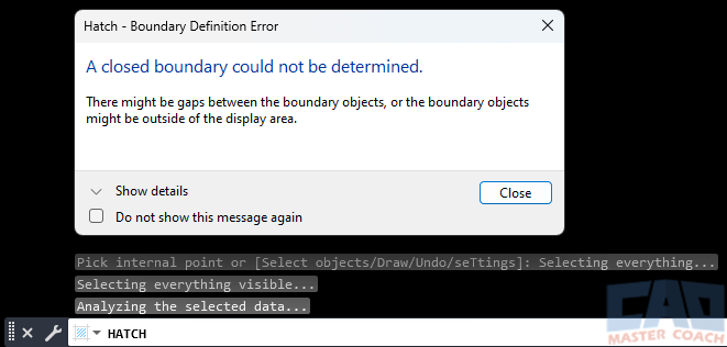
In AutoCAD, a HATCH is a pattern of lines and predefined shapes that repeat to fill an enclosed area. The area may be enclosed in many ways; a closed polyline, a series of lines / arcs / and circles that all touch in such a way to create a fully enclosed area, or any group of drawing objects arranged such that a fully enclosed area exists. If a point is selected that is not in an enclosed area, an error message appears.
When the HATCH command is initiated, a new tab appears on the ribbon which is activated and the focus changes to the Hatch Creation tab. The Hatch Creation tab is removed when the HATCH command is no longer active.
There are six tabs on the Hatch Creation tab:
1. Boundaries
AutoCAD requires a boundary around the area the hatch is being placed.
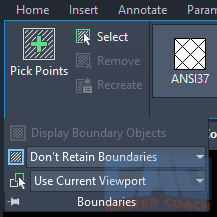
The initial selection of the boundary can be done in two ways.
- Pick Points: Select a point inside of an area that is entirely closed.
- Select: Select objects that collectively make a closed area. The objects do not need to be continuous or connected at their ends.
Additional Buttons:
- Remove will remove an object from the boundary selection.
- Recreate will create a polyline boundary around the area to be hatched and can associate the boundary with the hatch, if desired.
- Display Boundary Objects will highlight and display the objects that make up the boundary around the hatch.
- Don’t Retain Boundaries / Retain Boundaries – Polyline / Retain Boundaries – Region will indicate which of these three options to occur.
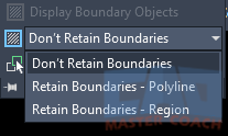
- Use Current Viewport will either use all objects in the boundary set or all objects in the current viewport to evaluate the objects to create the boundary when selecting Pick Points.
2. Pattern
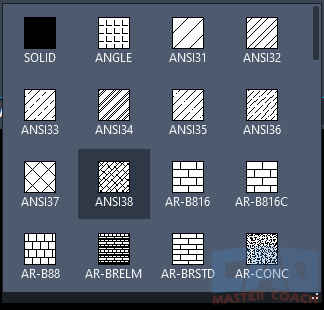
AutoCAD has several pre-defined hatch patterns that come with the software when it is installed.

Clicking on the double down arrow at the lower right shows more predefined hatch patterns. Clicking on one of these will select the hatch pattern to be used.
3. Properties
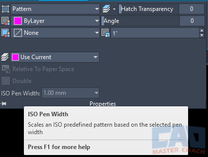
The Properties tab is where the properties of the hatch are modified.
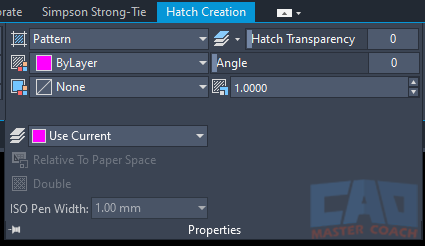
A HATCH in AutoCAD has ten properties that are assigned to it and can be changed.
3.1 Pattern
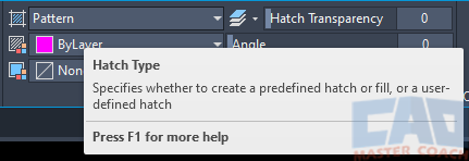
Pattern defines the hatch type. There are four choices of Hatch Type: Solid, Gradient, Pattern, User Defined.
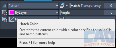
3.2 Hatch Color
Hatch Color allows the color of the hatch to be selected. The hatch color may be set to By Layer, By Block, or a custom color.
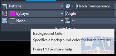
3.3 Background Color
Background Color changes the color of the background of the hatch. None or a custom color can be selected. In the image below, None is selected.
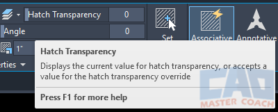
3.4 Hatch Transparency
Hatch Transparency sets the transparency level of the hatch. A transparency level of 0 indicates the hatch pattern is fully displayed and a transparency level of 100 indicates the hatch is fully transparent.
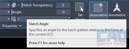
3.5 Hatch Angle
Hatch Angle changes the angle at which the Hatch is drawn. An angle of zero is shown in the image below. Any angle between 0 degrees and 360 degrees my be selected.
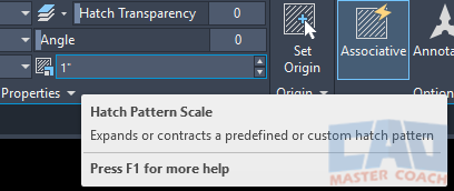
3.6 Hatch Pattern Scale
Hatch Scale changes the scale at which the Hatch is drawn. Larger numbers will scale the hatch pattern larger.
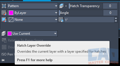
3.7 Hatch Layer Override
Hatch Layer Override sets the layer the hatch pattern will be placed on. In the image below, Use Current is selected. If the hatch pattern is to be placed on a layer other than the current layer, select the layer from the pull-down menu.
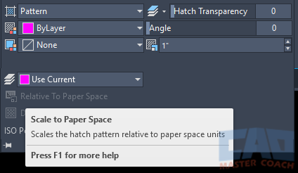
3.8 Scale to Paper Space
Scale to Paper Space will scale the hatch pattern to the Paper Space units. By default, the hatch pattern is scaled to the Model Space units.
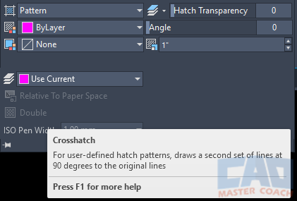
3.9 Crosshatch
Crosshatch will draw a second set of lines 90 degrees to the original lies for user defined hatch patterns. In the image below, Double is selected.
3.10 ISO Pen Width
ISO Pen Width will scale a predefined ISO hatch pattern based on the selected pen width.
4. Origin
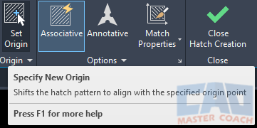
Every Hatch Pattern has an origin from which the pattern starts or originates from. By default, the origin of all hatch patterns is the origin of the UCS. To select a new origin point for the hatch, select the Set Origin button on the Origin Tab.
In addition, six predefined locations can be selected for the origin of the hatch to be.
- BL – Sets the origin of the hatch to be at the Bottom Left of the rectangular extents of the hatch.
- BR – Sets the origin of the hatch to be at the Bottom Right of the rectangular extents of the hatch.
- TL – Sets the origin of the hatch to be at the Top Left of the rectangular extents of the hatch.
- TR – Sets the origin of the hatch to be at the Top Right of the rectangular extents of the hatch.
- Center – Sets the origin of the hatch to be at the Geometric Center of the rectangular extents of the hatch.
- Origin – Sets the origin of the hatch to be at the current origin of the UCS.
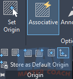
In addition, after a new hatch origin is selected it can be saved as the new Default Origin for future hatches.
5. Options
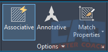
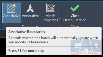
Options Tab displays three buttons at the top of the ribbon: Associative, Annotative, Match Properties.
5.1. Associative
An Associative hatch will update its shape when its boundaries are changed, where a hatch that is not associative will not update its shape when the boundaries are changed.
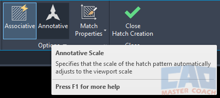
5.2. Annotative
An Annotative hatch will automatically adjust its scale to the scale of the viewport.
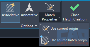
5.3. Match Properties
Match the properties of an existing source hatch with the option to use the current hatch origin or match the origin of the source hatch.
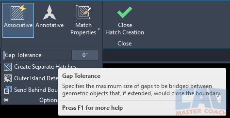
5.4 Gap Tolerance
Gap Tolerance specifies the maximum gap between drawing objects that would close the boundary if they were extended.
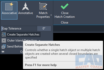
5.5 Create Separate Hatches
When more than one hatch area is selected in a single HATCH command, Create Separate Hatches sets if all hatches are to be drawn as separate objects, or all hatches will be one object and all hatches are highlighted when one hatch area is selected.
5.6 Island Detection
AutoCAD can detect closed areas inside of the area selected to hatch. A closed area inside of the outer closed is called an island.
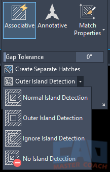
- Normal Island Detection – Hatches islands inward from the area detected in the pick point.
- Outer Island Detection – Hatches the area between the outermost boundary and the first boundary inside the outer boundary.
- Ignore Island Detection – Hatches everything inside the outermost boundary, ignoring any objects or islands inside the boundary.
- No Island Detection – Turn off island detection and use the Legacy Island detection method. Legacy island detection is manual island detection and inner islands are manually selected.
5.7 Boundary
Boundary indicates the location of the hatch relative to the boundary. When new objects are created, they are placed on top of existing objects. AutoCAD allows objects to be brought on front of other objects or sent behind objects. The hatch can automatically be placed in front of the boundary or behind the boundary at the time the HATCH is created.
The order of how objects are stacked in the drawing is called the Draw Order. Changing the draw order serves to make the drawing more visually appealing by bringing objects that need to be emphasized to the top and objects that are secondary parts of the drawing to the back.
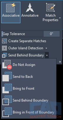
- Do Not Assign – The hatch is drawn in its default draw order.
- Send To Back – The hatch is sent to the back of all drawing objects.
- Bring To Front – The hatch is brought to the front of all drawing objects.
- Send Behind Boundary – The hatch is placed behind the Hatch Boundary.
- Bring In Front Of Boundary – The hatch is placed in front of the Hatch Boundary.
6. Close
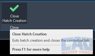
Selecting Close will close the hatch creation tab and end the HATCH command.
