AutoCAD EXTEND Command
EXTEND Command Access
COMMAND LINE: EXTEND

DEFAULT KEYBOARD SHORTCUT: EX
RIBBON: HOME | DRAW TAB | EXTEND

Introduction to AutoCAD EXTEND
The EXTEND command in AutoCAD is used to extend lines, polylines, circles, and arcs to another line, polyline, circle, or arc defined as the boundary edge.
How to Use The EXTEND Command in AutoCAD
The TRIM and EXTEND commands are in the same pull-down menu in the Modify tab, perform nearly the opposite actions of each other, and are so closely related that when one of the commands is active, pressing the SHIFT key morphs the active command into the other.
When the EXTEND command is initiated, the first expected input is the Boundary Edge. If no boundary edges are selected, and the ENTER key is pressed again ENTER is pressed twice in a row, one time to initiate the command, then a second time, every line, Pline, circle, arc, and ellipse becomes a boundary edge.
Pictured below is what the Dynamic Input looks like when the EXTEND command is initiated.

The EXTEND command has two selection modes and switching between them occurs immediately after initiating the command by entering ‘O’ at Dynamic Interface command line. Quick Selection or Standard Selection modes can either be picked with the mouse or by entering Q for Quick Selection or S for Standard Selection respectively. AutoCAD remembers the last selection mode chosen and that will be your default mode until the other is chosen.
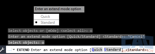
Standard Selection mode is selected in the picture above for the EXTEND command.
The selection mode refers to how the objects that are to be trimmed will be selected. In Standard selection mode, EXTEND uses object selection methods described on the Three Methods to Select AutoCAD Objects page; direct, window, and crossing.
If the Quick selection method is selected, then every object becomes a boundary edge. To extend objects in the drawing, either directly select each object or hold down the left mouse button and drag the mouse around to cross every object you wish to extend. There is no limitation on the shape drawn that will select the objects to be extended to.
In the image below, the EXTEND command is being used in Quick Select mode. Note the shape of the white boundary line. It is an irregular shape and every line it crosses is extended to the next object.

EXTEND Options
1. Boundary edges
Enter B to select the cutting edge or cutting edges. If boundary edges have already been selected, and you wish to select a new set of boundary edges, enter B at the Dynamic Input and new boundary edges can be selected.
2. Fence
In the EXTEND command, a Fence is a line that is drawn that extends every object that crosses the Fence. In the picture below, the Fence is the white dashed line. Notice that the only line being extended is the lower magenta line; this is because the upper magenta line doesn’t have anything beyond the end of it to extend to.

3. Crossing
Using the Crossing option will initiate the selection window to be a Crossing Window, regardless of the first direction the mouse is moved after the initial mouse click. Typically, when the mouse is moved to the right after the initial mouse click, a Window is created with the first direction the mouse moves is to the right. The Crossing option overrides that and allows the first mouse movement to the right to be a Crossing and not a Window.
In the image below, note that the first mouse movement was to the right and both ends of the lower magenta line will be extended.

4. mOde
Using the Mode option enables the user to switch between Quick and Standard selection modes while the command is active. The Mode option can be selected before drawing objects are selected and can also be selected while the command is active.

5. Project
The Project option allows the projection mode to be changed.
- None: Only objects that interest with defined cutting edges are trimmed
- UCS: Only objects on the current XY plane of the UCS will be trimmed
- View: Only objects on the current view are cutting edges.

6. Edge
The Edge option can either be set to Extend or No Extend. To switch between the two modes, press E then select either Extend or No Extend.

When Edge is set to Extend, objects that are being extended will be extended to the projected intersection of another object. In the image below, the horizontal magenta line that has the pickbox hovering over it is being shown to extend only to the implied intersection with the vertical line above it. Notice that the two lines do not actually intersect, however there is an implied intersection which the line is being extended to.

All Commands
Command Categories

Create
Explore all AutoCAD Create commands in one place. Learn how to use LINE, CIRCLE, ARC, POLYLINE, BLOCK, HATCH, and more with tutorials and practical examples.

Modify
Your complete guide to AutoCAD Modify tools—ERASE, TRIM, EXTEND, MOVE, ROTATE, OFFSET, FILLET, and more—with tips and workflows.

Notation
Complete guide to annotation in AutoCAD: text, dimensions, leaders, tables, zoom/pan basics, and clipboard tools.

All Commands
Browse every AutoCAD command in one place with this complete A–Z index. Quickly find command pages for LINE, ERASE, ZOOM, and more, with clear explanations and tips for efficient drafting.
Modify Commands