AutoCAD DIM Command
DIM Command Access
COMMAND LINE: DIM

DEFAULT KEYBOARD SHORTCUT: D
RIBBON: HOME | ANNOTATION PANEL | DIM
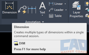
Dimension AutoCAD Objects with DIM Command
Placing dimensions on drawing objects effectively communicates information about the drawing. Use the DIM command to place dimensions on drawing objects and organize the dimensions to make them readable.
There are two primary methods to place a dimension in AutoCAD:
2. Dimensioning between two points.
Similar to TEXT and MTEXT needing to have Text Styles defined before using the commands, DIM requires Dimension Styles to be defined prior to using it.
After initiating the DIM command, simple dimensions can be placed on objects in two ways, either by selecting the object and AutoCAD or selecting two points on the same or different objects.
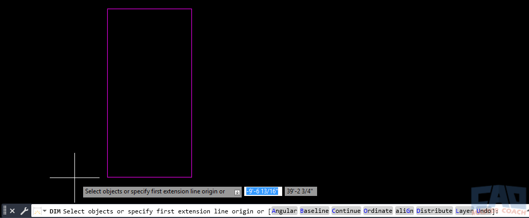
Selecting an Object to Dimension
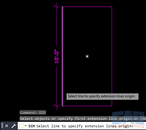
To select an object to place a dimension on, initiate the DIM command and hover the mouse over the object to be dimensioned. AutoCAD will show a preliminary dimension that can be moved to the desired location with the mouse.
Several actions can be performed in one instance of the DIM command. The DIM command will stay active after each action and prompt for the next action until ENTER or ESC is pressed while waiting for the next action to be entered.
In the image below, the pickbox is hovering over the left vertical line of the rectangle, and the 10’-0” dimension that is being displayed is a preliminary dimension. Clicking on the vertical line will make it a permanent dimension and the mouse can be moved to the left or right to place the dimension in the desired location.
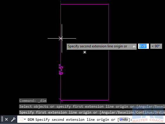
Selecting Points on an Object to Dimension
To select two points to place a dimension between, initiate the DIM command and select the first point. Then move the mouse in the direction the dimension will be measuring. As the mouse is being moved away from the first point, a dimension is placed between the first point and the crosshairs with the preliminary dimension. As the crosshairs move, the dimension continuously changes. In the image below, the crosshairs is 6’-5” away from the first point.
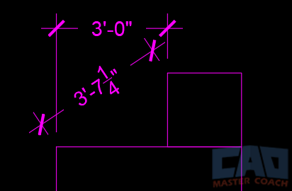
In addition, the points that the dimension is being placed between do not need to be on the same object. The dimension will measure the distance between two points and the dimension line will be parallel to the line between these points. If the points that a dimension is being placed between are not on the same orthogonal plane, the DIM dimension will measure the actual distance between the points, and not the orthogonal distance. In the image below, the 3’-7” dimension is a DIM dimension and the 3’-0” dimension is a DIMLINEAR dimension.
Eight DIM Options
In addition to selecting an object to be dimensioned or selecting the points to place a dimension between, the DIM command has eight options:
1. Angular
Angular measures the angle between objects, or between points on the same object that are not colinear. When Angular is selected, three options are presented.

1.1 Arc
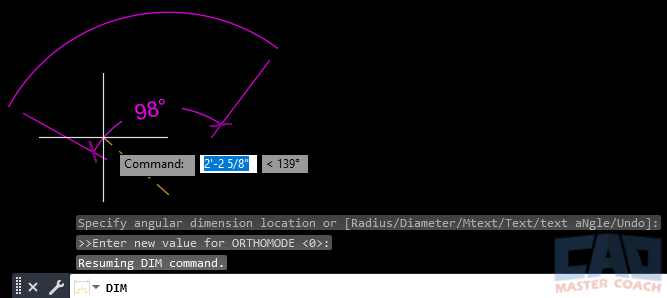
DIM | Angular | Arc option measures the angle the arc sweeps. Click on the arc and the dimension contains two lines that extend from the ends of the arc to the center. The angle is measured on these extension lines. In the image below, the center of the arc is at the end of the yellow dashed line. Drag the mouse to place the dimension at the desired location.
1.2 Circle
DIM | Angular | Circle option measures the angle between two points on a circle with the center of the circle being the vertex of the angle.
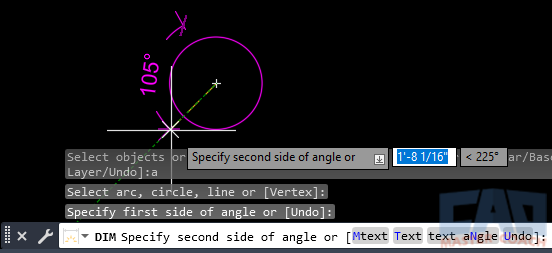
To use Circle, click on a circle and then select the first point on the circle to begin measuring the angle from. Then select the second point on the circle the angle will be measured. In the image below, the point closer to the top of the circle was selected first, and the second point is towards the lower left. In this case the angle between of the projected lines from the chosen points to the center of the circle between these two points is 105 degrees.
1.3 Line
DIM | Angular | Line measures the angle between two lines. The do not need to intersect and they cannot be parallel.
In the image below, after selecting the Angular option, the bottom horizontal line was selected first and when the pickbox is hovering over the angled line, the angle between them appears. Pick the second line, then move the mouse to place the angle dimension.
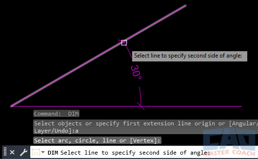
If the selected lines are parallel, a message is displayed that says “Lines are parallel. Select another line to specify the second side of angle:” When this happens, the pickbox returns to be able to select another line.

2. Baseline
A Baseline dimension is a series of dimensions that all originate from the same point and each measure to a different point along a common line. When initiating the DIM | Baseline, there is an option to enter a new Offset. The Baseline Offset is the vertical space between the dimensions in the Baseline dimension set. In this case, the default value is the height of the Text Style used in the current Dimension Style.

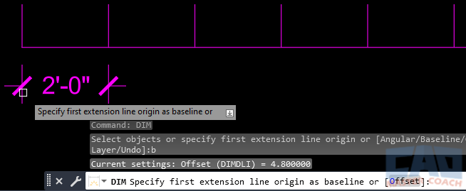
To create a Baseline dimension, first create a typical dimension using the DIM command. Then in a new instance of the DIM command, select Baseline, then AutoCAD asks to “Specify first extension line origin as baseline”. In the image below, the left extension line is being selected and will be the baseline for the Baseline dimensions.
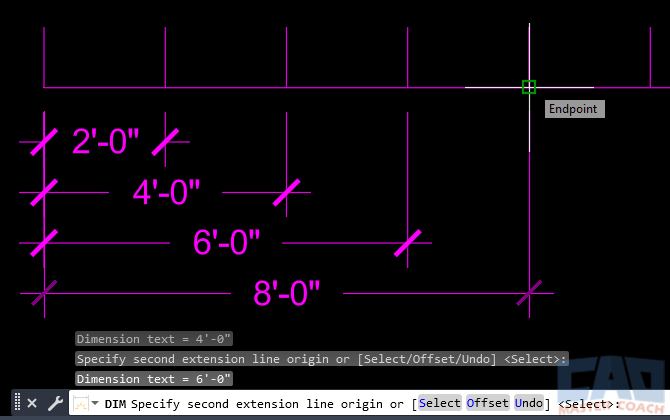
In the image below, the baseline dimensions are automatically created from the left extension line of the original dimension and then each point has been selected along the horizontal line to each of the vertical lines. The dimensions added by the DIM | Baseline command are the 4’-0”, 6’-0”, and the 8’-0” is being shown as a preliminary dimension because the pickbox is over the endpoint of the next vertical line. Note how close the text is because the Offset is set to the default of the text height.
In the image below, the information being displayed is the Offset is 4.8 inches. The Offset option has been entered and a new value of 10 inches is being entered, which will increase the vertical space between the dimensions.

Shown in the image below is the result of increasing the Offset to 10 inches. When creating a Baseline dimension, the vertical spacing between the dimension lines has increased and is easier to read.

3. Continue
DIM | Continue is a series of dimensions where each dimension begins where the previous dimension ended. Unlike Baseline where each dimension is in a different vertical space, DIM | Continue dimensions are all located on the same vertical plane.
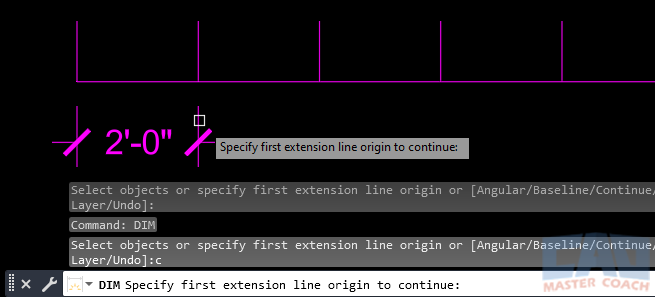
To use DIM | Continue, first create a dimension that additional dimensions are to continue from. As shown in the image below, when the Continue option is selected, AutoCAD asks for the first extension line origin. Select the extension line on the side of the original dimension that you want to continue placing dimensions. In this case, the right extension line of the original 2’-0” dimension is selected.
After selecting the right extension line of the original 2’-0” dimension, AutoCAD creates another dimension that originates from the end of the previously created dimension. In the image below, the preliminary dimension is shown to be 2’-7 1/4", and will be the exact dimension when one of the lines is selected.
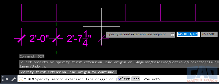
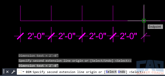
As shown below, the DIM | Continue command will keep asking for the next location to dimension to until ENTER or ESCAPE is pressed.
4. Ordinate
DIM | Ordinate dimensions measure the distance from a known base point to objects in the drawing. The known base point is always the origin of the UCS, so when using DIM | Ordinate, the origin of the UCS must be changed to a location on the base object that the ordinate dimensions are being placed on.
The first step in using DIM | Ordinate is to change the UCS to the location all vertical and horizontal ordinate dimensions will be measured from. In the image below, the UCS is moved to the bottom left corner of the rectangle.

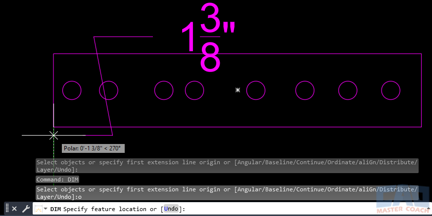
After changing the UCS to the desired location, initiate the DIM | Ordinate command and notice where the dimension line is initially located. In the image below, the crosshair is 1 3/8” below the bottom left corner of the rectangle, where the UCS was moved to and the ordinate dimension that is being displayed is 1 3/8” with a jogged line associated with it. Moving crosshair around will move the location of the dimension and the shape of the jog.
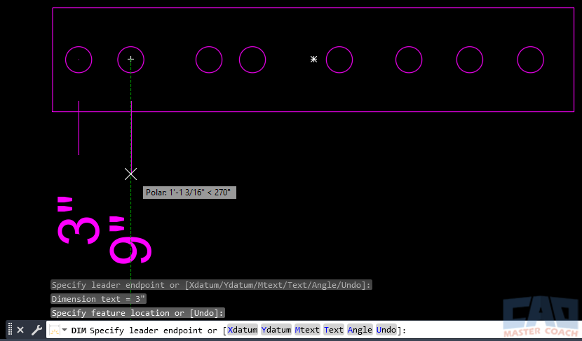
In the image below, the center of the first circle was selected for the object to dimension and then a location below the rectangle was selected to place the dimension. The command remained active and the center of the second circle was selected, and the crosshair is moved below the rectangle to place the 9” dimension. These dimensions indicate the center of the holes are 3” and 9” horizontally from the lower left corner of the rectangle.
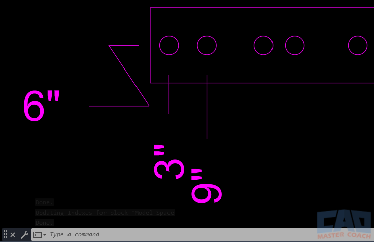
In the image below, the center of the first circle was clicked again and this time the mouse was moved up to indicate a vertical ordinate dimension is to be placed on the object. In this case, the center of the circle is 6” from the bottom of the rectangle. Also, the lines marking the dimension may also have a jog in them. To create a jog in the Ordinate dimension line, move the crosshair such that it does not directly align with the object being dimensioned and a jog will automatically be added to the dimension line.
After completing a DIM | Ordinate command, it is good practice to return the UCS to its previous location, or the WCS. To change the UCS back to the World Coordinate System, enter UCS at the command line, then W for World Coordinate System.

5. Align
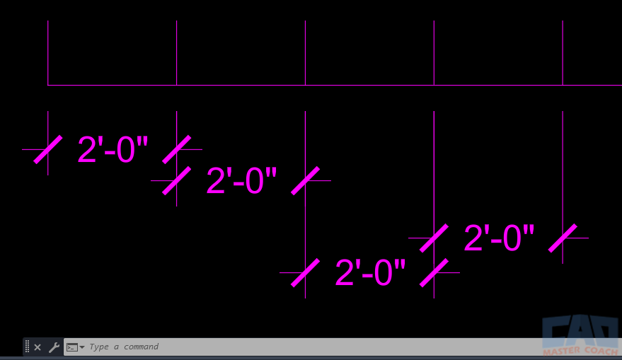
DIM | Align is used to move existing dimensions so they all align with each other. Use Align to bring dimensions that are parallel to the same line. Sometimes dimensions are placed on a drawing haphazardly, and this is an easy way to align a group of dimensions to make them present better on the drawing.
In the image below, the dimensions are not aligned and are placed haphazardly. Use DIM | Align to bring all dimensions in line with a base dimension.
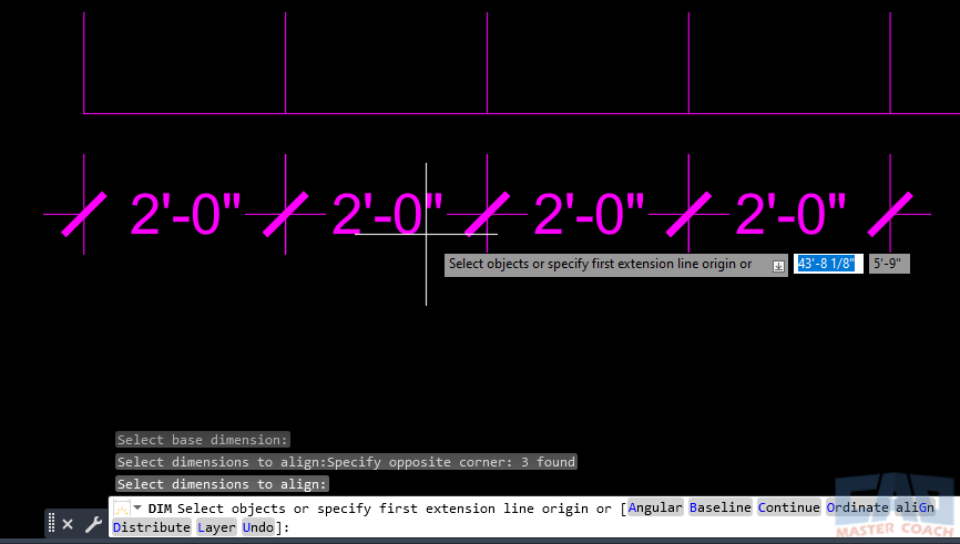
As shown in the image below, DIM | Align was selected, the left dimension was selected as the Base Dimension, then the other three dimensions were selected to be aligned with the Base Dimension, resulting in all dimensions being aligned.
6. Distribute
DIM | Distribute will evenly space existing dimensions in the drawing. There are two methods to use Distribute.
6.1 Equal
When existing dimensions are not aligned, Equal will equally Distribute the dimensions between the two dimensions that are closest to the object and furthest from the object being dimensioned. At least three dimensions are required.
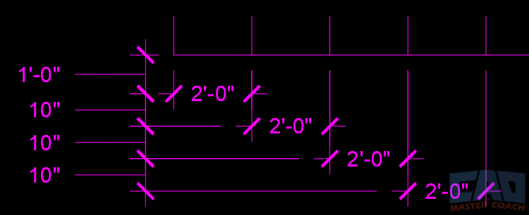
In the image below, all of the 2’-0” dimensions are unevenly spaced, and the space between them is shown at the left side of the image. Using DIM | Distribute | Equal option will evenly distribute all of the 2’-0” dimensions between the upper and the lower, because they are the closest to and furthest from the objects being dimensioned.
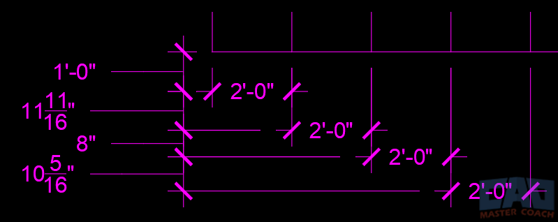
In the image below, the DIM | Distribute | Equal option is initiated and all of the 2’-0” dimensions are all selected.
To use DIM | Distribute | Equal, initiate the DIM command, then select Distribute, then select Equal. Then, select all dimensions that are to be equally distributed. The two dimensions that are closest and furthest from the objects being dimensioned will remain in their original locations and all dimensions between them will be moved so they are equally distributed.
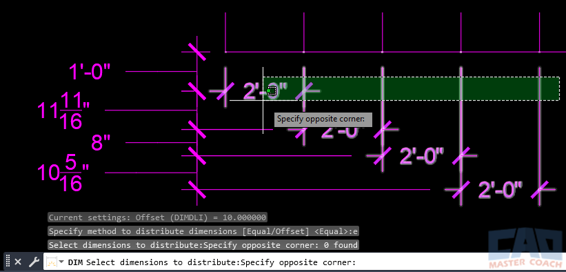
After completion of the DIM | Distribute | Equal command, all of the 2’-0” dimensions are equally distributed between the upper and lower dimensions. All dimensions are now equally spaced at 10”, as shown in the dimensions at the right side of the image.
6.2 Offset
When existing dimensions are not aligned, Offset will Distribute the dimensions at an Offset distance specified during the command.
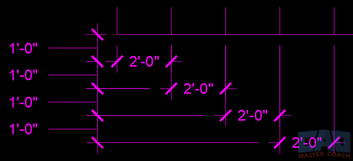
In the image below, all of the 2’-0” dimensions are unevenly spaced, and the space between them is shown at the left side of the image. Use DIM | Distribute | Offset option to space all of the 2’-0” dimensions 1’-0” (12”) apart.

To use DIM | Distribute | Offset, initiate the DIM command, then select Distribute, then select Offset. Then, enter “O” again to enter an Offset distance. In the image below, 12” was entered as the Offset distance. Next, select the Base Dimension, which is the dimension that all other dimensions will be offset from.
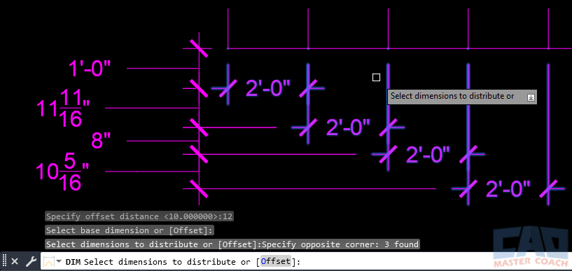
Press ENTER to Distribute the dimensions, then press ENTER again to exit the command. As shown in the image below, all 2’-0” dimensions are Distributed to a 1’-0” (12”) Offset spacing.
7. Layer
By default, all dimensions will be placed on the current layer when they are created. If you want to put all dimensions on another layer as they are created, use DIM | Layer to select the layer all dimensions are to be placed on.
In the image below, DIM | Layer has been initiated and a new Layer that all dimensions can be entered. The dimension layer can either be typed in at the command line, or entered by selecting an existing object on the layer all new dimensions are to be placed on. The two lines and the “LAYER TEXT” are on a layer called TEXT. By clicking on any of these objects, the Dimension Layer will be TEXT and all new dimensions will be placed on the text layer.

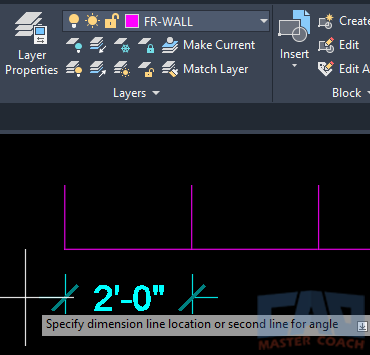
In the image below, the current layer is FR-WALL as seen near the top center of the image in the Layer pull-down, and because the Dimension Layer has been set to the TEXT layer, and the default color for the TEXT layer is cyan, we can see the 2’-0” dimension is being placed on the TEXT layer while FR-WALL.
To set the Dimension Layer to use the current layer, when specifying the Dimension Layer, enter a “.” (a period) when asked to enter the Dimension Layer.
The Dimension Layer can also be set using the DIMLAYER system variable. To change the DIMLAYER system variable, enter DIMLAYER at the command line and follow the prompts.
8. Undo
DIM | Undo will undo the last action while the command is active. The DIM command will remain active after each action and UNDO can be used to reverse the actions taken one at a time as part of the current DIM command.
In the image below, DIM | Undo was used to reverse a dimension that was placed in the drawing. After placing the dimension, the DIM command remained active and the DIM | Undo command was used.

If the DIM command is completed and another instance is started, the DIM | Undo will not undo any actions from a previous instance of the command. If the UNDO command is initiated after completion of a DIM command, all actions performed during the entire instance of the DIM command will be undone in one UNDO command.

