
Qleader
AutoCAD QLEADER Command
COMMAND LINE: QLEADER

DEFAULT KEYBOARD SHORTCUT: LE
RIBBON: HOME | ANNOTATE TAB | QLEADER

It should be noted that the QLEADER Button shown is not in the ribbon by default. See how to add the button to your Ribbon.
AutoCAD QLEADER
QLEADER is a quick and simple way to easily place dimensions in AutoCAD drawings. If you are looking for an easy way to place leaders in your drawings, QLEADER is a good choice because of its simplicity.
Similar to creating text or dimensions in AutoCAD, before a Leader can be created, leader styles must be created. Leader styles are created when dimension styles are created.
A Leader in AutoCAD consists of a line or polyline and a leader annotation. The leader annotation can be Mtext, a copy of an object, a tolerance, or a previously defined Block reference.
Creating a QLEADER in AutoCAD
Step 1 - Initiate the QLEADER Command
To create a Qleader, initiate the QLEADER command. As shown in the image below, AutoCAD waits for the first point of the leader, which is where the leader points to. Alternatively, the Settings can be changed by entering S.

When the first point is selected, AutoCAD draws the Arrowhead defined by the leader style and waits for the second point to be selected in the dynamic interface. If the crosshairs are too close to the first point, the arrowhead will not be drawn until the mouse is moved far enough away from the initial point so there is enough room to draw the arrowhead.
Step 2 - Click on the First Point
In the image below, the crosshairs are moved far enough away from the initial point so the arrowhead is shown, along with the distance and angle from the initial point the crosshairs are from the initial point and AutoCAD is waiting for the second point to be specified.

Step 3 - Move the Mouse Far Enough Away From the First Point to Allow the Arrow to Be Created and Click On the Second Point
After the second point is selected, a third point needs to be pickled. Traditionally, the third point is a horizontal line from the second point. In the image below, the third point is shown to be 0’-6” at an angle of 180 degrees from the second point.
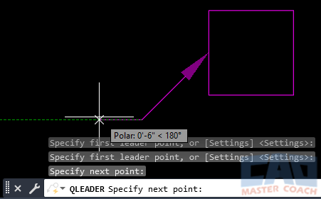
Step 4 - Move the Mouse in a Horizontal Direction and Click On the Third Point, Where the Text Will Be Located
After the third point is picked, either another segment to the leader can be added by picking another point, or the text width can be entered. It should be noted that in the image below, the option to enter Mtext is selected in the settings.
Entering a text width of zero (0) will create an Mtext area that will be one line and infinite width. The width of the Mtext area can be changed after entering the text in the Mtext box.

In the image below, a text width of 0 has been entered. Enter the first line of the Mtext, or optionally, press ENTER to initiate the MTEXT editor.

Step 5 - Enter the Leader Text
In the image below, ENTER has been pressed and the Mtext window is activated. Note the left and right arrows adjacent to the empty Mtext box awaiting text to be entered.

Shown in the image below, text is entered in the Mtext box and the Mtext box is still active waiting for more text to be entered. If the ENTER key is pressed, the cursor moves to the next line below, If the ESC key is pressed, all text entered will be erased and the QLEADER command will be canceled.

Step 6 - End the QLEADER Command
To end the QLEADER command and exit back to the command line, click anywhere in the drawing that is outside of the Mtext box. In the image below, the point where the crosshairs are shown was selected and the QLEADER command ended.

To edit the Mtext associated with a Qleader, double click the Mtext and edit the text as any other Mtext.

Step 7 - Optionally, Change the Width of the MTEXT Box
To change the width of the Mtext area and activating word wrapping, grab the edge of the Mtext area that is opposite the leader and move to the left or right. Note in the image below that when the width of the Mtext box is changed, it now has a defined width and a ruler appears to indicate the width of the Mtext box.

QLEADER SETTINGS
To change the QLEADER Settings, enter S after initiating the command and the QLEADER dialog box appears.

The QLEADER dialog box has three tabs. The Annotation along with the Leader Line & Arrow tabs are always present. The Attachment tab is only present when the Mtext Annotation Type is selected.
1. Annotation Tab – Qleader Settings

The Annotation tab has three settings area to select from:
1.1 Annotation Type
Select the Annotation Type associated with the Qleader.
1.1.1 MTEXT
Enter Mtext as described in the MTEXT Command.
1.1.2 Copy an Object
Copy an existing Mtext, Text, Tolerance, or Block to the end of the leader line. The object that is copied will be associated with the Qleader.
1.1.3 Tolerance
Displays the Tolerance Dialog box, where tolerance settings are selected.
1.1.4 Block Reference
Select an existing block defined in the drawing. The block is associated with the leader line.
1.1.5 None
Creates a leader without an Annotation associated with it.
1.2 MTEXT Options
Greyed out when Mtext is not selected as the Annotation type.
1.2.1 Prompt for Width
Prompts for the width of the Mtext area when after the leader has been created. This option is selected in the command description above.
1.2.2 Always Left Justify
All Mtext will be left justified regardless of the leader location or direction.
1.2.3 Frame Text
Draws a frame around the Mtext associated with the Qleader.
1.3 Annotation Reuse
Indicated if Annotations are to be reused when creating new Qleaders.
1.3.1 None
Annotations will not be reused and each new Qleader will require its own annotation to be created.
1.3.2 Reuse Next
The next annotation created will become the new default annotation for all subsequent Qleaders.
1.3.3 Reuse Current
Reuses the current Annotation. Note, this option is automatically selected when Annotation is reused after selecting Reuse Next.
2. Line Leader & Arrow Tab – Qleader Settings
The Line Leader & Arrow tab has four settings to select from:
2.1 Leader Line
Select whether to make the lines that form the leader are Straight lines or curved Splines. A Spline is a type of Pline.
2.2 Number of Points
Enter a maximum number of line segments, or check the No Limit box to remove limits on the number of line segments a Qleader can have.
2.3 Arrowhead
Select the type of arrowhead to be used for the Qleader. In addition to the many predefined arrowheads, a user defined block may be selected as the arrowhead.
2.4 Angle Constraints
The angle for the first and second line segments may be constrained to the following:
- Any Angle – Any angle may be selected.
- Horizontal – The line segment must he horizontal.
- 90 – Line segments are constrained to angles that are multiples of 90 degrees.
- 45 – Line segments are constrained to angles that are multiples of 45 degrees.
- 30 – Line segments are constrained to angles that are multiples of 30 degrees.
- 15 – Line segments are constrained to angles that are multiples of 15 degrees.
3. Attachment Tab – Qleader Settings

The Attachment Tab indicates where the Mtext associated with the Qleader will be placed relative to the leader. AutoCAD differentiates the text placement settings based on which side of the leader the Mtext is placed. For Mtext placement on each side of the Qleader, there are five selections to choose from. A selection must be made for Mtext placement on each side of the Qleader.
1. Top of Top Line
Places the last segment of the Qleader at the top of the top line.
2. Middle of Top Line
Places the last segment of the Qleader at the middle of the top line.
3. Middle of the Multi-Line Text
Places the last segment of the Qleader at the middle of the Mtext area.
4. Middle of Bottom Line
Places the last segment of the Qleader at the middle of the bottom line.
5. Bottom of Bottom Line
Places the last segment of the Qleader at the bottom of the bottom line.
Additionally, check the Underline Bottom Line box to underline the bottom line of every Mtext area associated with a Qleader.
Attachment Settings:
- Text on Left Side – Middle of Bottom Line
- Text on Right Side – Middle of Top Line
Note the last line segments of each leader is placed at the middle of either the top line or the middle of the bottom line as indicated in the settings.
