Layer
AutoCAD LAYER Command
COMMAND LINE: LAYER

DEFAULT KEYBOARD SHORTCUT: LA
RIBBON: HOME | LAYERS TAB | LAYER PROPERTIES
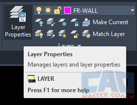
AutoCAD LAYER
Using LAYER Command in AutoCAD
Layers are used to organize drawing objects. Because layers can be assigned different properties, drawing objects on different layers can be made to have different visual appearances.
By using layers in, objects in the drawing can be organized by visual appearances. In addition, Layers can be shown or not shown at any time to show objects that are important and hide objects that are not important to be displayed.
Every object in an AutoCAD drawing must be on one layer, and each object can be on only one layer. The layer an object is on is a property in the same way the color of an object is a property of that object.
It can be very useful to organize objects in groups of layers sorted by a common text tag in the layer names. As shown in the image below, the layers shown in the drawing below all start with a short common text string. The layers where the Main Floor Framing will be placed all start with FM- while the layers where the Roof Framing will be placed all start with FR-.
Organizing the layers this way makes sorting them and plotting easier to organize. If all layers that all relate to each other begin with similar text strings, it makes selecting them all at once easier to do.
When the LAYER command is initiated, the Layer Properties Manager dialog box is displayed.
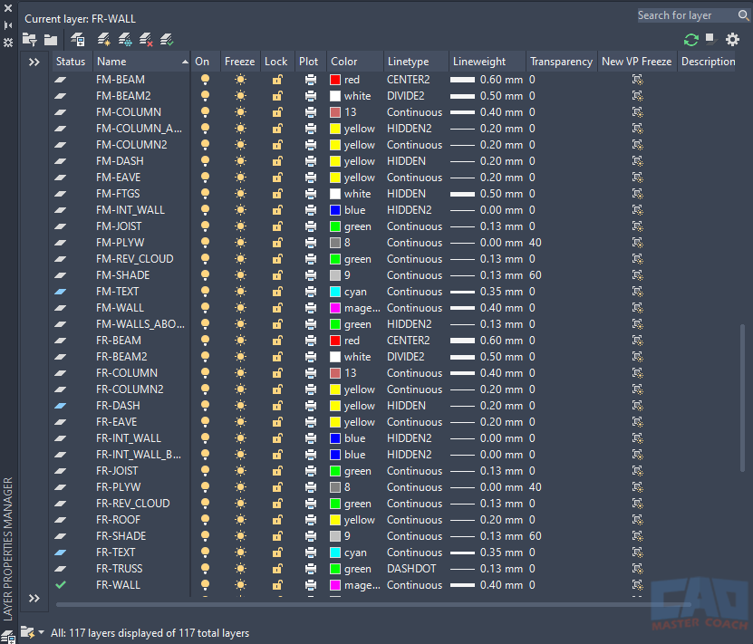
When in Model Space, every layer has 11 properties which must be defined plus a description that is optional to define. When the Layer Properties Manager dialog box is activated in Paper Space, six additional properties appear, and they all begin with VP, indicating they apply to the active Viewport.
NOTE: The system variable SHOWLAYERUSAGE is set to 1 for the status symbols to be displayed properly. If SHOWLAYERUSAGE is set to 0, all Status symbols are shown as the Layer Contains Objects.
Model Space Layer Properties
1. Status
1.1 

Double click on a layer name to make it the current layer. The current layer is where all new objects are drawn on.
1.2 

The blue filled in icon is displayed if there are any objects on the layer.
1.3 

The grey icon is displayed if there are no objects on the layer.
2. Name
Name of the Layer. To edit the layer name, highlight the layer in the Layer Properties Manager and press F2.
3. On / Off
3.1. 

Layers that are On are visible on the screen and will plot.
3.2 

Layers that are Off are not visible on the screen and will not plot and AutoCAD continues to monitor the location of all objects on layers that are Off. Layers that are Off are included when the REGEN or REGENALL commands are used, possibly affecting the computer’s performance.
4. Freeze / Thaw
Freeze and Thaw affects layers in all viewports.
4.1 

Layers that are Frozen will not be visible on the screen and will not plot. When a layer is Frozen, it is not included in the REGEN or REGENALL commands, improving the computer’s performance.
4.2 

Thawed layers are visible, are available to plot, and are included in the REGEN and REGENALL commands.
5. Lock / Unlock
5.1 

Objects on Locked layers are visible and not able to be edited.
5.2 

Objects on Unlocked layers are visible and can be edited.
6. Plot / Do Not Plot
6.1 

Objects on layers with Plot turned on will plot, if they are also turned On and Thawed.
6.2 

Objects on layers set to Do Not Plot are still visible on the screen and will not plot.
7. Color

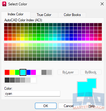
When the color icon is pressed, the color palette window appears. In the Index Color tab, two areas are shown. At the top of the window, 250 colors can be selected; if one of these colors is selected, the color number is displayed. At the bottom of the window, 15 colors can be selected; if one of these colors is selected, the color name is displayed.
8. Linetype

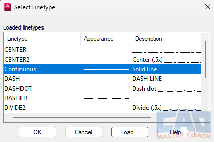
When the Linetype is selected, the Select Linetype palette appears. A new linetype can be selected. Additionally, more linetypes can be added to the drawing which can be selected for layers and drawing objects.
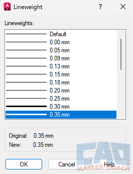
9. Lineweight

Select the desired Lineweight for the layer from the Lineweight Palette.
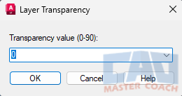
10. Transparency

Change the transparency level to the desired value. The number entered is the percentage of transparency, with 90 being the maximum allowable transparency. A transparency of 0 means the layer will be displayed on the screen and plotted with no transparency. Using a higher transparency can be useful to deemphasize objects in the drawing.
11. Description
Double click in the description area for the layer to enter a layer description. Entering a description does not affect how the layer behaves, it is used to make notations about the layer to assist the user to have information about the intended use of the layer.
Additional Paper Space Layer Properties
The following Layer Properties only appear when the Layer command is initiated while in Paper Space. These properties only change the properties of the active Viewport. It can be useful to freeze and thaw different layers in multiple Viewports to display and hide drawing objects in each Viewport.
- VP Freeze
- VP Color
- VP Linetype
- VP Lineweight
- VP Transparency
- New VP Freeze
Special AutoCAD Layers
Two layers are present in every AutoCAD drawing that cannot be deleted or have their name changed. Each has special properties that are important to other functions.
Layer 0
Layer 0 is most effectively used when creating Blocks and X-Refs.
When objects in a Block are placed on Layer 0 as part of the Block definition, those objects inherit the properties of the layer the Block is inserted on.
If a block is created with all of the objects on Layer 0, those objects will be drawn with the Layer 0 Properties when in the Block Editor. Subsequently, when that Block is placed on a layer with a different color and different linetype, the block will be displayed with the properties of the layer the Block is placed on, not the properties of Layer 0. If objects comprising a Block are placed on any Layer other than Layer 0, those objects retain the properties of their original layer.
DefPoints Layer
The Defpoints Layer contains definition points for the dimensions in the drawing. If it does not exist yet, it will be automatically created when the first dimension is created.
Objects on the Defpoints layer will appear on the screen and will not be printed or plotted to any output.
