Selecting Drawing Objects
Three Methods to Select AutoCAD Objects
Many AutoCAD command requires the user to select one or more objects in the drawing. Selecting objects can be done in one of three ways:
1. Direct Selection
Objects can be directly selected one at a time by hovering the pickbox over the object and left clicking the mouse. After selecting an object, AutoCAD waits for another object to be selected. If all desired objects are selected, press ENTER to advance to the next phase of the command.
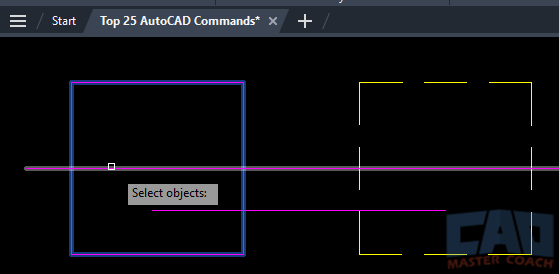
In the picture below, the magenta box has already been selected and the longer horizontal line will be selected when the left button of the mouse is clicked. The lower magenta line and the yellow dashed box are not selected.
2. Window Selection
Objects selected in a window must be entirely inside of the selection window. If an object is only partially in the selection window, it will not be part of the selection group. To select objects in a window, left click the mouse at any random point on the screen, then move the mouse to the right of the originally selected point. Then, move the mouse up or down to create the selection window.
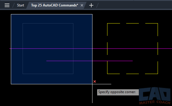
In the image below, the initial point that created the selection window is the upper left corner of the highlighted selection window. The mouse was then moved to the bottom right, and the cross hairs are shown. Notice that the magenta box is selected and is greyed out, it is part of the selection group because it is entirely within the selection window, and the two magenta lines are not selected because they are not entirely within the selection window. Note that a window selection is defined by a solid line around the window and has a blue background.
Get the Top 35 AutoCAD Commands for FREE
3. Crossing Selection
Any objects in a crossing selection that are partially or entirely in the Crossing are selected at part of the selection group. Unlike a Window where objects must be entirely within the Window, only part of the object needs to be in the Crossing to be selected as part of the selection group; any object that crosses the Crossing boundary is selected. To create a Crossing, left click on the mouse at any point in the drawing and then move the mouse to the left of the original point. Then move the mouse up or down to create the Crossing.
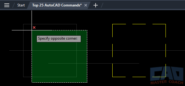
In the image below, the initial point in the Crossing is the lower right corner of the Selection, and the mouse is moved to the left and up to create the Selection; the cross hairs are still shown at the upper right corner of the selection. Notice that the magenta box at the right and both horizontal lines are greyed out as they are selected, and none of those objects are entirely within the Crossing. Note that the Crossing is defined by a dashed line around the Crossing and has a green background.
How to Unselect Objects
Any object that has been selected and is part of the selection group can be unselected by holding the SHIFT key while selecting the object(s) you wish to remove from the selection group.
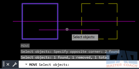
In the image below, two objects were initially selected for the MOVE command, the magenta square on the left and the lower horizontal magenta line. While holding the SHIFT key, the lower horizontal line was directly selected. Note the information AutoCAD is outputting regarding the number of selected objects. Initially the feedback is that two objects were found, then the next line is one object is removed, leaving one object total in the selection group. This is to be expected because two objects were initially selected, then one was removed.
