AutoCAD BREAK Command
BREAK Command Access
COMMAND LINE: BREAK

DEFAULT KEYBOARD SHORTCUT: BR
RIBBON: HOME | MODIFY TAB | BREAK
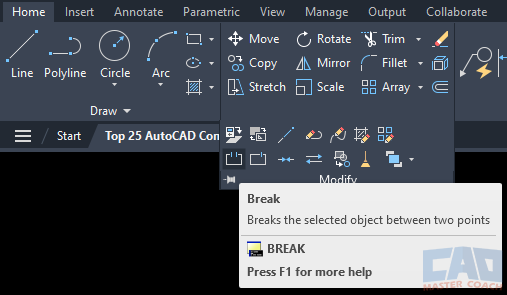
How to Use BREAK Command in AutoCAD
The BREAK command in AutoCAD is used to break an object into two separate objects.
When the BREAK command is initiated, AutoCAD shows a pickbox and waits for an object to be selected. The location at which the object is selected is where the object will be broken, then a crosshair appears to wait for the second point to be selected. The second point is entered in the Dynamic Input.
As shown in the picture below, the upper magenta line was selected and then the mouse was moved to the right. The space between where the first selection point is and the crosshair will be removed from the original line and two lines are formed from the original line.
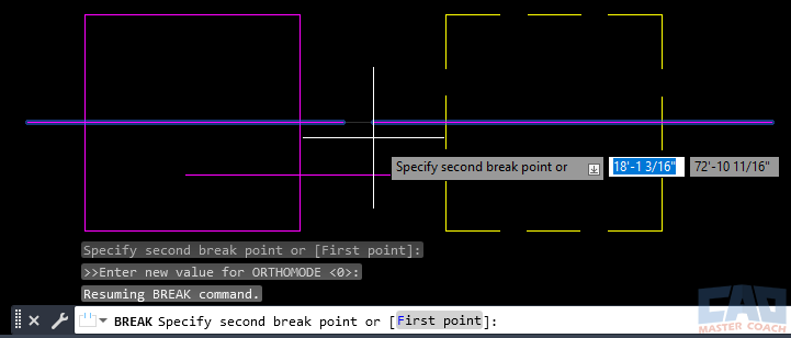
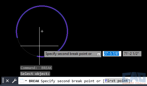
The BREAK command can be used on lines, polylines, arcs, circles, closed polylines, and more. When BREAK is used on a circle, the result is an arc. In the image below, BREAK is being used on the circle; the first point that was picked is the left side of the break, and the mouse was moved to the right to create the break in the circle. The result will be an arc when the command is finished. Using BREAK on a closed polyline behaves the same way as on a circle.
