Block
AutoCAD BLOCK Command
COMMAND LINE: BLOCK

DEFAULT KEYBOARD SHORTCUT: B
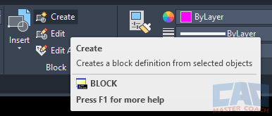
RIBBON: HOME | BLOCK TAB | BLOCK

AutoCAD BLOCK
Creating custom complex drawing objects using the BLOCK command can aide in creating drawings faster and with more accuracy.
In AutoCAD, a block is a collection of drawing objects which can include lines, arcs, circles, text, hatches, attributes, and other blocks. Each object in the block can have different properties such as layers, colors, line weights, and more. Use the BLOCK command to create a new block.
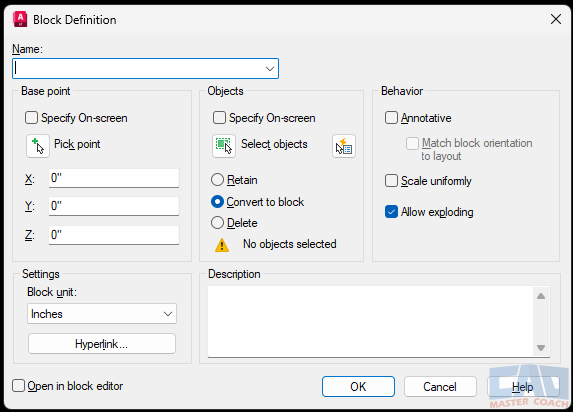
When initiating the BLOCK command, a window titled Block Definition opens with seven areas to provide input to define the block.

1. Name
Each block must have a unique name. Enter the name of the block here. If a name of an existing block is entered, you will be asked if you want to redefine the block.
2. Base Point
The base point of a block is the point where the block will be inserted when selected with the cursor or entered on screen. There are three options:
- Specify On-Screen: Specify the Base Point on the screen when selecting the objects that are to be included in the block.
- Pick Point: Pressing this button immediately send you to the drawing screen to pick the Base Point.
- X/Y/Z: Enter the X,Y,Z coordinates of the desired Base Point.
3. Objects
The objects are the drawing objects that are included in the block. The objects can be selected before the command is initiated or the objects can be selected after the command has begun. Two methods to select:
- Specify On-Screen: Check the Specify On-Screen box and then press OK to be sent to the drawing screen to select the objects that will be included in the block. In addition, if the Specify On-Screen button in the Base Point input area is checked, AutoCAD will ask for the Base Point to be selected before selecting the objects that make up the block.
- Select Objects: Pressing the Select Objects button will send you to the drawing screen to select the objects that make up the block. Pressing Enter will bring you back to the Block Definition window.
There are three options when selecting objects of the block:
- Retain: The original objects will remain as individual objects, and a block will be created.
- Convert to Block: The objects that are selected to create the block will become part of the block being created.
- Delete: A block will be created with the selected drawing objects and the original objects will be deleted.
4. Behavior
There are three checkboxes in this area:
- Annotative: If this box is checked, the block will be annotative. An annotative block will automatically adjust their scale to match the viewport scale or the drawing scale. Creating an annotative block is beyond the scope of this class.
- Scale Uniformly: When inserting a block, there is an option to scale the block. This option indicates to scale the X, Y, and Z axis uniformly.
- Allow Exploding: A block can be exploded and converted to the objects that make up the block. Checking this box allows a block to explode, unchecking this box makes the block not able to be exploded.
5. Settings
There are two settings to select:
- Block Unit: One of several predefined units can be selected. Some of the most commonly used units are inches, feet, millimeters, or meters, among many other units options. In addition, a block can also be set as unitless.
- Hyperlink: Inserting a hyperlink in a block will enable the block to be connected to a web page on the internet, a web page on your company’s intranet, an image, a file such as a pdf or other data file, another AutoCAD drawing, or it can even create an email preaddressed to whomever you wish.
6. Description
Enter a description in the Description text box that will be displayed in the Properties tab. The description entered is stored with the block.
7. Open In Block Editor
If this box is checked, the block editor will be opened, and the block being created will be able to be edited.

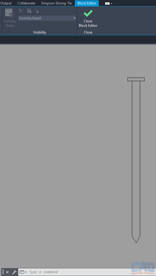
When the Block Editor is open, the background changes to a grey color, and the Ribbon changes to the Block Editor Ribbon. Using the Block Editor, changes to blocks can be made, and when they are saved all instances of the block are updated.
