
PEDIT JOIN Explained: How to Combine Lines and Polylines Correctly
If you have ever tried to join lines into a single polyline and wondered why AutoCAD simply refuses to cooperate, you are not alone. The PEDIT JOIN option is one of the most powerful — and most misunderstood — tools in AutoCAD. On the surface, it looks simple: select objects, choose JOIN, and move on. In practice, small gaps, mismatched geometry, or property differences often cause JOIN to fail silently.
This article explains exactly how PEDIT JOIN works, why it fails, and when FILLET is actually the fastest and safest way to “join” geometry before using PEDIT. If you are searching for answers to “why won’t PEDIT join my lines,” this page is written specifically for you.
Before diving in, you may also want to review these related articles:
- PEDIT Command (overview)
- LINE vs POLYLINE
- FILLET Command
- JOIN Command
These pages work together as a cluster and will help you avoid common polyline mistakes.
PEDIT JOIN vs FILLET — Quick Decision Guide
| Situation | Best Tool | Why It Works |
|---|---|---|
| Objects already touch exactly | PEDIT JOIN | Combines connected geometry into a single polyline without modifying shape |
| Endpoints almost touch | PEDIT JOIN (with fuzz distance) | Fuzz distance allows near-touching endpoints to join |
| Visible gap or overlap exists | FILLET (Radius = 0) | Trims or extends geometry to create a true intersection |
| JOIN fails repeatedly | FILLET → PEDIT JOIN | FILLET fixes geometry first so JOIN can succeed |
| Objects have different layers or properties | Either (select carefully) | Resulting polyline inherits properties of the first object selected |
What the PEDIT JOIN Option Actually Does
The JOIN option inside PEDIT allows you to combine multiple objects into one continuous polyline. When JOIN is successful, AutoCAD converts the selected objects into a single polyline object made up of connected segments.
There are two critical limitations to understand up front:
- PEDIT JOIN does not modify geometry
It will not trim, extend, or move objects to make them connect.
- Objects must already touch
Endpoints must coincide exactly, or fall within an allowable tolerance (fuzz distance).
If geometry only looks connected on screen but does not mathematically share endpoints, JOIN will fail.

Lines must actually touch for PEDIT JOIN to work
Objects That Can Be Joined with PEDIT
PEDIT JOIN works with several common object types, but not all geometry is treated equally.
Objects that can be joined:
- Lines
- Arcs
- Open polylines
- A combination of lines and arcs
When these objects are joined successfully, the result is always a single polyline.
Objects that cannot be joined directly:
- Circles
- Ellipses
- Splines
These objects must be converted or redrawn before they can participate in a PEDIT JOIN operation.
Understanding this limitation alone explains many failed JOIN attempts.
How to Use PEDIT JOIN (Step-by-Step)
The PEDIT JOIN workflow is straightforward once you understand what AutoCAD is checking behind the scenes.
- Start the PEDIT command
- Select a line or polyline
- If prompted, choose Yes to convert the object to a polyline
- Select the JOIN option
- Select the objects you want to join
- Press Enter to complete the operation
At this point, AutoCAD evaluates:
- Whether endpoints touch
- Whether the objects are coplanar
- Whether gaps fall within the fuzz distance
If any of these conditions fail, JOIN will not occur.

The JOIN option combines connected geometry into one polyline
Why PEDIT JOIN Fails (Most Common Causes)
This is where most users get stuck. JOIN usually fails for reasons that are not immediately visible.
The most common causes include:
- Endpoints that do not actually touch
- Tiny gaps or overlaps between objects
- Geometry drawn on different planes
- Slight Z-value differences
- Fuzz distance set too small
- Locked layers or referenced geometry
Zooming in tightly often reveals gaps that were invisible at normal zoom levels.

Small gaps often cause JOIN to fail
Fuzz Distance Explained
Fuzz distance is a tolerance that allows PEDIT JOIN to connect endpoints that are almost touching.
This exists because:
- Imported drawings are rarely perfect
- Traced geometry often contains rounding errors
- Real-world CAD files accumulate small inaccuracies
A small fuzz distance can allow JOIN to succeed without forcing you to redraw geometry.
Best practices for fuzz distance:
- Start with a very small value
- Increase only as needed
- Avoid large fuzz values that could create unintended joins
Fuzz distance helps with near-misses, but it cannot fix geometry that clearly does not meet.
Using FILLET to “JOIN” Geometry (The Efficient Fix)
When two polylines do not share a common endpoint, FILLET is often the fastest and safest way to create a valid connection.
This is a critical workflow concept:
FILLET does not technically merge objects into one polyline — but it creates the intersection required for joining.
When FILLET Is the Better Tool
Use FILLET when:
- There is a visible gap between polylines
- Geometry overlaps instead of meeting
- PEDIT JOIN fails repeatedly
- Objects must be trimmed or extended
By setting the fillet radius to zero, AutoCAD trims or extends the objects to meet at a sharp corner.
Once geometry truly connects, PEDIT JOIN becomes reliable.

FILLET creates true connections before joining
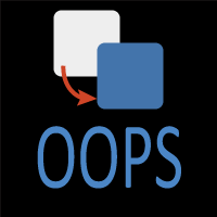
Property Inheritance: A Critical Rule to Understand
There is one extremely important rule that applies when geometry is joined — whether through PEDIT JOIN or a FILLET-assisted workflow.
When multiple objects are combined into a single polyline, the resulting polyline inherits the properties of the first object selected.
This includes:
- Layer
- Color
- Linetype
- Lineweight
- Transparency
This behavior often surprises users when geometry suddenly “changes layers.”
Best practice:
Always select the object with the desired properties first when joining geometry.
This single habit prevents a lot of cleanup work later.
PEDIT JOIN vs Other Tools (Comparison Table)
| Command | Why It Matters |
|---|---|
| PEDIT JOIN | Combines already-connected geometry into one polyline |
| JOIN | Joins objects without polyline editing options |
| FILLET | Trims or extends geometry to create connections |
| EXTEND | Forces endpoints to meet |
| TRIM | Removes overlaps before joining |
Understanding when to use each tool is far more effective than forcing JOIN to work.
Best Practices for Reliable Joining Workflows
- Zoom in before joining
- Clean geometry first
- Use object snaps deliberately
- Flatten geometry when needed
- Check the Properties palette after joining
- Do not rely on visual alignment alone
PEDIT JOIN is reliable when geometry is clean — and frustrating when it is not.
Related Commands
| Related Command | Purpose |
|---|---|
| PEDIT | Edit polyline geometry |
| JOIN | Combine objects |
| FILLET | Create clean intersections |
| TRIM | Remove excess geometry |
| EXTEND | Force connections |
| OVERKILL | Remove duplicate objects |
Ways to Use Pedit
Learn how to convert lines to polylines in AutoCAD using PEDIT and FILLET. Understand why JOIN fails, when FILLET works, and how to clean geometry efficiently.
Learn how PEDIT JOIN works in AutoCAD, why it fails, how fuzz distance affects results, and when FILLET is the best way to connect polylines correctly.
Learn how to use the PEDIT command in AutoCAD to convert lines, join geometry, calculate areas, and create clean offsets.
Learn the most common PEDIT mistakes in AutoCAD, why JOIN fails, how fuzz distance works, and how to fix broken geometry before converting lines to polylines.
Frequently Asked Questions (FAQ)
Because the endpoints do not actually touch. PEDIT JOIN does not trim or extend geometry.
Yes. Endpoints must coincide or fall within the fuzz distance.
A tolerance that allows near-touching endpoints to join.
Yes. Polylines can contain both straight and curved segments.
No. It only joins geometry that already meets.
Yes. FILLET trims or extends geometry to create a valid connection.
Because FILLET modifies geometry before attempting a connection.
The resulting polyline inherits the properties of the first object selected.
Only if the objects are coplanar and share matching Z-values.
Command Categories

Create
Explore all AutoCAD Create commands in one place. Learn how to use LINE, CIRCLE, ARC, POLYLINE, BLOCK, HATCH, and more with tutorials and practical examples.

Modify
Your complete guide to AutoCAD Modify tools—ERASE, TRIM, EXTEND, MOVE, ROTATE, OFFSET, FILLET, and more—with tips and workflows.

Notation
Complete guide to annotation in AutoCAD: text, dimensions, leaders, tables, zoom/pan basics, and clipboard tools.

Drafting Aids
Learn AutoCAD’s Drafting Aids and Precision Controls—OSNAP, Ortho Mode, Polar Tracking, Object Snap Tracking, and Dynamic Input. Improve accuracy, speed, and control with this complete guide.

All Commands
Browse every AutoCAD command in one place with this complete A–Z index. Quickly find command pages for LINE, ERASE, ZOOM, and more, with clear explanations and tips for efficient drafting.
Modify Commands


Ways to Use Pedit