AutoCAD Tangent Arc Tutorial: Draw Smooth Curves with FILLET and Tangent Snaps
Introduction
Smooth transitions are a cornerstone of clean CAD drafting. Whether you’re laying out a roadway, modeling a piping system, or designing a mechanical component, you’ll often need to connect straight lines or curves seamlessly. That’s where tangent arcs come in.
In AutoCAD, there isn’t a direct “Tangent Arc” option in the ARC command anymore. Instead, tangent arcs are created using tools such as FILLET, Circle with Tangent Snaps, or Polyline continuation. These methods ensure arcs connect smoothly without sharp corners, maintaining geometric continuity and readability.
This article explains what tangent arcs are, when to use them, and how to draw them step by step using multiple methods. We’ll also look at verification strategies, common mistakes, and professional tips to get the most from tangent arcs.
Comparison of Arc Creation Methods in AutoCAD
AutoCAD provides several different ways to create arcs, and each method is suited to a particular type of design problem. Some approaches emphasize precision, such as defining a fixed radius, while others focus on flexibility, like passing through three points or constraining a curved length. Tangent arcs occupy a special place because they guarantee smooth continuity with existing geometry. The table below compares the four primary arc creation methods, their best applications, and their limitations.
|
Method |
How It Works |
Best Used For |
Limitations |
Verification Tools |
|
Define an arc by start point, end point, and a known radius. |
Precise radius control in architectural details, doors, or mechanical parts. |
Requires known radius before drawing; not ideal for fitting geometry. |
DIMRADIUS, Properties palette. |
|
|
Create an arc through three chosen points. |
Survey layouts, scanned drawing traces, or irregular geometry fits. |
Radius is unpredictable; bulge direction depends on pick order. |
Properties palette, DIMRADIUS. |
|
|
Adjust or constrain an arc so its curved distance matches a set length. |
Pipe bends, fabrication cut lengths, road curves specified by arc length. |
No direct Start–End–Length input; requires Properties, LENGTHEN, or DIMARC. |
Properties palette, LIST, DIMARC. |
|
|
Tangent Arc |
Insert an arc tangent to existing geometry using FILLET, circle tangent snaps, or polylines. |
Roadway transitions, piping bends, smooth mechanical profiles. |
Pick order matters; FILLET fails if radius is impossible; TAN OSNAP must be enabled. |
Visual inspection, Object Snap, DIMRADIUS. |
What Is a Tangent Arc?
A tangent arc is a curve that touches another object at exactly one point while maintaining smooth continuity. Unlike arcs defined by radius or three points, tangent arcs prioritize seamless transitions. They are indispensable when your design requires motion or flow to continue uninterrupted.
- In civil engineering, tangent arcs guide roadways, sidewalks, and driveways.
- In mechanical design, they define cams, gears, and smooth part profiles.
- In architecture, they ensure clean joins between walls or landscaping features.
- In piping/ductwork, tangent bends prevent abrupt flow changes.
The key is continuity: a tangent arc has no break in direction where it meets another object.
Method 1: Drawing Tangent Arcs with FILLET (Most Common)
The FILLET command is the fastest and most reliable way to create tangent arcs in AutoCAD. It automatically inserts an arc of a given radius between two selected objects, trimming or extending them as needed.
Steps:
- Draw two objects that will be joined (e.g., two intersecting lines).
- Type FILLET (shortcut F) and press Enter.
- At the command prompt, type R and press Enter.
- Enter the desired radius value.
- Select the first object.
- Select the second object.
AutoCAD trims/extends the geometry and creates a perfect tangent arc between them.
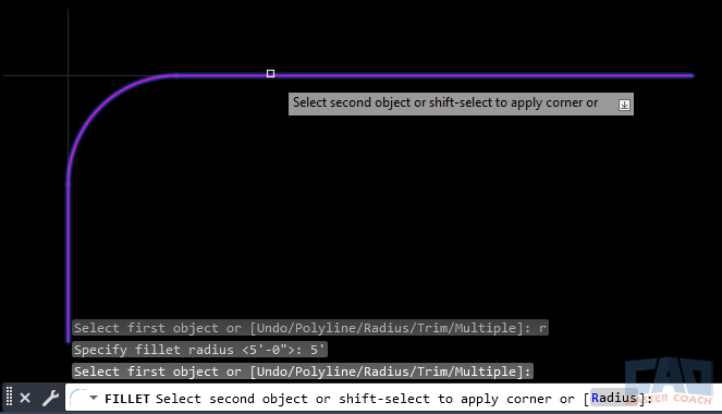
Using FILLET to insert a tangent arc between two lines.
In the image above, the FILLET command is being used to create an arc with a radius of 5’-0” that is tangent to both original lines. As described in the FILLET command page, depending on how the FILLET command settings are set, the extension lines will either be trimmed away, or they can be kept. In this case, they are trimmed, and that can be seen by the grey line extensions shown projecting from each of the original magenta-colored lines.
Best Use Cases:
- Consistent bends in roadway design.
- Standard corner radii in mechanical or architectural layouts.
- Quickly smoothing corners in polylines or frames.
Method 2: Using a Circle with Tangent Object Snaps
Sometimes you need more control than FILLET provides — for example, when the arc must be tangent to two circles or to a line and a circle. In these cases, drawing a circle first and trimming it down works better.
Steps:
- Type CIRCLE or click the Circle tool.
- Specify the radius or diameter of the circle.
- Activate Object Snap (F3) and ensure Tangent (Tan) is enabled.
- Pick two objects (lines, arcs, circles) using the Tangent snap. AutoCAD positions the circle so it touches both tangentially.
- Use TRIM or EXTEND to remove the unnecessary portions, leaving only the arc segment you need.
This method gives you flexibility, especially for more complex geometry.
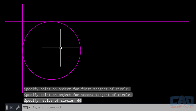
Positioning a circle tangent to two objects before trimming.
Shown in the image above is a circle drawn using the TAN-TAN-RADIUS option in the CIRCLE command. The two lines are selected as the objects for the circle to be tangent to, then a radius is entered, in this case the radius is 60. After the circle is drawn, the TRIM command can be used to erase the unwanted portion of the circle resulting in an arc remaining that is tangent to the two lines selected.
Best Use Cases:
- Tangent connections between arcs and circles.
- Geometric constructions in mechanical profiles.
- Scenarios where the tangent arc is part of a larger circular feature.
Method 3: Polyline Arc Continuation
A lesser-known trick is to draw tangent arcs as part of a polyline. When you’re in the middle of the PLINE command, you can switch from drawing a line to drawing an arc, and AutoCAD automatically assumes tangency.
Steps:
- Type PLINE and press Enter.
- Start drawing a line segment.
- At the next prompt, type A for Arc.
- Specify the endpoint of the arc.
The arc continues from the line and is tangent by default. This workflow is excellent for chaining geometry into a single editable polyline.
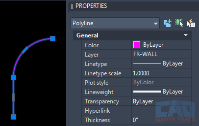
Switching from a line to an arc in a polyline with tangency preserved.
In the image above, an arc has been continued from the end of a POLYLINE, and the arc is tangent to the line. Both the line and arc retain their original geometry, and the result is a single object, the polyline.
Best Use Cases:
- Creating road centerlines or profiles.
- Drafting furniture or mechanical outlines.
- Any case where continuous geometry is easier to manage.
Verifying Tangency
Even when using trusted commands, always confirm tangency:
- Zoom in visually: Ensure no corner exists where the arc meets the line.
- Object Snaps: Hover with OSNAP to confirm tangent snap points exist.
- DIMRADIUS/DIMARC: Dimension the arc to confirm its radius and placement.
- LIST Command: Reports properties, including tangency constraints for circles and arcs.
For critical designs, verification is just as important as creation.
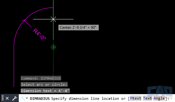
Using DIMRADIUS to check tangent arc geometry.
Shown in the image above is a DIMRADIUS verifying the radius of the arc, confirming it is tangent to the original line.
Common Mistakes to Avoid
- Forgetting to set the radius: FILLET defaults to the last-used radius. Always check before clicking.
- Objects too far apart: If the distance between objects is too large for the chosen radius, AutoCAD throws an error.
- Not enabling Tangent snaps: When using the circle method, forgetting to toggle TAN OSNAP causes placement errors.
- Confusing chord vs. tangent: Tangent arcs are defined by smooth continuity, not just endpoint connections.
Pro Tips for Tangent Arcs
- Use FILLET with radius = 0 to quickly join two lines at a sharp corner.
- Create standard tangent arc blocks (e.g., 1m radius bend) for repeated use.
- Combine constraints in the Parametric tab to keep arcs tangent even after geometry shifts.
- For roadway design, keep all arcs in polylines so the path edits as one unit.
- Save tangent arcs in templates for standard fabrication details.
Real-World Example: Parking Lot Curb Return
Suppose you’re laying out a parking lot with drive aisles connecting to a street. The local code requires a 27’-6” curb return radius.
- Draw the street edge and the driveway edge as straight lines.
- Run FILLET → Radius = 27’-6”.
- Pick the two lines.
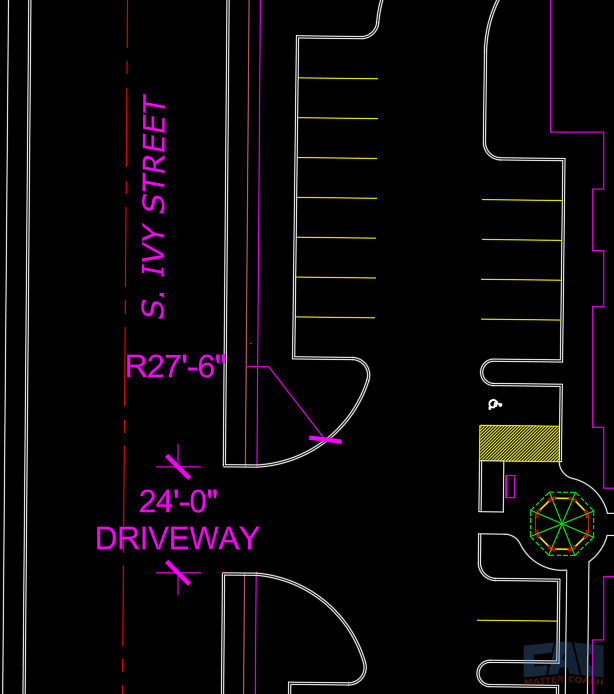
A tangent arc forming a 27’-6” curb return at a driveway entrance.
Shown in the image above is a driveway entrance to a parking lot. The DIMRADIUS command shows the correct radius of the arc that creates the curb defining the driveway.


