Arc by 3 Points in AutoCAD | CADMasterCoach
Introduction
Among the different methods available for creating arcs in AutoCAD, the Arc by 3 Points command stands out for its simplicity and flexibility. Instead of defining a radius, angle, or center point, this approach relies on three user-selected points that the arc must pass through. By doing so, it allows drafters to shape curves that respond directly to design intent, reference geometry, or visual judgment.
This method is particularly useful when working in conceptual design phases, when precision dimensions are not yet known but visual proportions are important. It also excels in renovation or tracing workflows, where you may have to reproduce curves from an image, survey, or scanned background drawing. Because the arc is defined by three points, it provides an intuitive, hands-on approach to curve creation that beginners find easy to grasp while still giving experienced CAD users the flexibility to adjust complex layouts quickly.
Need an exact radius instead? See Arc by Radius.
Accessing the 3 Point Arc Command
AutoCAD offers multiple ways to launch the 3 Point Arc option. Knowing all of them ensures you can work efficiently no matter how you prefer to interact with the software:
- Command Line: Type ARC and press Enter, then type 3P or select the 3 Point option.
- Ribbon: Navigate to Home → Draw Panel → Arc dropdown → 3 Point Arc.
- Toolbar/Menu: Draw → Arc → 3 Point.
- Dynamic Input: If Dynamic Input is active, typing ARC will show the 3 Point option on-screen.
This flexibility means you can either rely on menus for visual navigation or stay fully keyboard-driven for speed.
Step-by-Step: How the 3 Point Arc Works
When using this method, AutoCAD asks you to pick three points in order:
1. First Point – Start of the Arc
This establishes the location where the arc begins. It may connect to existing geometry or start in open space.
2. Second Point – Control Point
The most critical step. The second point defines how much the arc “bulges” or curves. It doesn’t have to be located midway between the start and end — its placement determines the arc’s curvature.
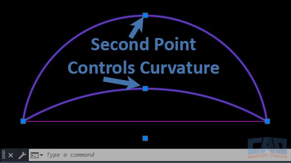
AutoCAD 3 point arc examples showing how the second point controls the amount of bulge in the curve.
By moving the grip at the midpoint of the arc, the bulge, or radius, is adjusted.
3. Third Point – End of the Arc
The final point defines where the arc terminates. Together, AutoCAD uses these three selections to mathematically define the curve.
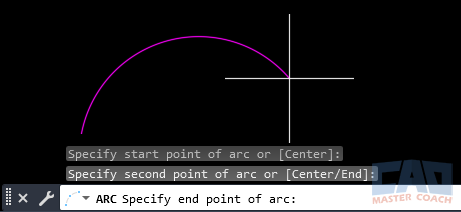
AutoCAD 3 point arc created step by step with three picked points defining the curve.
Unlike the Arc by Radius or Start-Center-End options, you don’t need to know numerical inputs. The system automatically creates the single possible arc that passes through all three points. This makes the command quick and versatile, especially when your goal is to “fit” geometry through known reference marks.
Practical Applications
The Arc by 3 Points method is more than just a beginner-friendly tool — it has broad use cases across drafting, architectural design, and engineering workflows. Let’s look at where it shines:
1. Conceptual Sketching
When starting a project, you may not yet know exact curve radii or center points. Using 3 Point Arc, you can sketch natural-looking curves that respond to the geometry around them. Landscape architects use this approach to shape paths and garden layouts. Civil engineers might quickly illustrate roadway bends before committing to precise radii.
2. Fitting Arcs Through Known Points
Sometimes you’re given two endpoints and a required pass-through location. For example, a bridge designer may know the two abutment points (start and end) and want the arc to pass through a survey benchmark. By defining all three, AutoCAD guarantees the curve hits the required location.
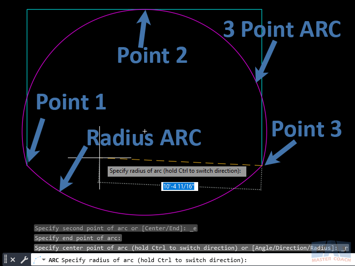
Comparison of AutoCAD arc by radius versus arc by 3 points showing difference in definition methods.
The image above illustrates one of the best uses of a 3 Point ARC. In the upper arc, the three points were selected, and AutoCAD will fit an arc that goes through all three points. The lower arc is an arc drawn by radius, and it can be difficult to fit an arc to three known points while trying to guess the correct radius.
3. Tracing from Background Files
When working with imported PDFs, raster images, or old scans, precise radii may not exist. The 3 Point Arc is the fastest way to replicate an arc drawn on paper. By clicking three reference spots along the existing curve, you can recreate accurate geometry for digital use.
4. Design Adjustments & Iteration
During refinement, designers often need to test several curve options. For example, adjusting the bulge of a curved roofline or roadway. The second point in the 3 Point Arc acts as a control handle — moving it slightly can change the visual balance without redrawing the entire curve.
5. Quick Curves in Detail Work
For interior layouts, cabinetry, or ornamental designs, 3 Point Arc helps create smooth curves without lengthy calculations. It’s particularly useful for freeform work that isn’t dimension-driven but still needs precision once snapped to reference geometry.
6. Educational & Training Value
For students learning AutoCAD, 3 Point Arc is often the first introduction to geometric flexibility. It demonstrates how a curve can be mathematically defined without formulas — just by choosing points. This helps learners connect CAD workflows to geometry concepts.
Tips & Tricks for Efficiency
- Use Object Snaps (OSNAP): Combine 3 Point Arc with END, MID, and INT snaps to ensure precise alignment. For example, snap the first and last points to line endpoints, then snap the middle point to an intersection.
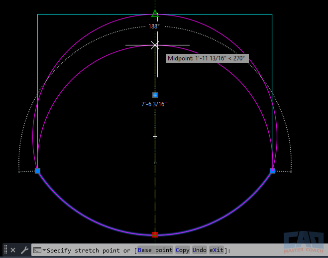
Using object snaps to create an AutoCAD 3 point arc aligned to geometry.
In the image above, the middle OSNAP point is used to adjust the lower arc to fit the desired points. In this case, the lower arc is being adjusted to have the same radius as the upper arc.
- Grip Editing: After placing the arc, select it to reveal grips. You can move grips to adjust curvature without redrawing.
- Combine with Polylines: Use the PEDIT command to join the arc with polylines, creating continuous paths for offsetting or extrusion.
- Check the Properties Palette: If you need numeric control later, the Properties palette lets you see start angle, end angle, radius, and length.
- Experiment with Second Point Placement: Moving the second point slightly up or down changes curvature dramatically. Try different placements to “tune” your design.
Related Commands & System Variables
- CIRCLE 3P: Works on the same principle but generates a full circle through three chosen points.
- ARC (Radius): Useful when precision radius values are needed. Compare when deciding between geometric accuracy and visual fit.
- PROPERTIES Palette: Lets you refine arc values after it is drawn.
- PEDIT: Convert arcs into polylines for complex editing.
- DYNAMIC INPUT: Makes point selection easier with on-screen prompts.
Common Mistakes to Avoid
While simple, the 3 Point Arc can trip up beginners if used carelessly. Here are common pitfalls and how to avoid them:
1. Poor Second Point Placement
The second point controls curvature. If chosen too close to the first or last point, the arc may look flattened or distorted. Always place it thoughtfully to achieve the intended bulge.
2. Forgetting Snaps Are Off
Without OSNAPs enabled, clicks may be slightly off target, producing misaligned arcs. For example, snapping to an intersection ensures accuracy, but a freehand click may cause errors. Always double-check snap settings before selecting points.
3. Confusing with Other Arc Methods
New users sometimes expect to input radius or angle after choosing points. Remember, this method only accepts three coordinates. If you need radius-based control, use the Start-End-Radius method instead.
4. Redrawing Instead of Editing
Beginners often delete arcs that don’t look right and redraw from scratch. A faster workflow is to use grip editing — drag the midpoint grip to adjust bulge, or use Properties for numeric edits.
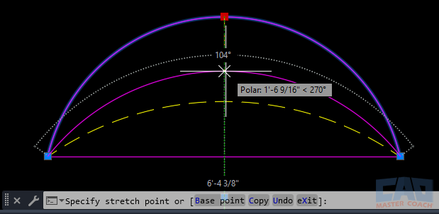
AutoCAD grip editing a 3 point arc by moving the midpoint grip to adjust curvature.
Editing an ARC is as simple as selecting one of the grips and moving it to a desired location. In the image above, the grip at the midpoint of the upper arc is being moved down and the yellow dashed arc is the desired arc. After moving the upper arc’s grip to the lower arc, the upper arc will match the lower arc’s shape.
5. Over-Snapping to Geometry
Too many snap constraints can force the arc into unintended alignments. For example, snapping the second point to the wrong midpoint could flip the arc unexpectedly. Keep an eye on the command line and snap symbols.
6. Not Checking Layer & Object Properties
Placing arcs on the wrong layer or with incorrect color/linetype is a frequent oversight. Especially in collaborative projects, always confirm layer assignments after drawing.
7. Overlooking Alternatives
Sometimes 3 Point Arc is not the best tool. For arcs that must match a specific radius or tangency, radius- or direction-based arc options are better suited. Knowing when not to use this method is just as important as knowing when to use it.
