How to Draw an Arc by Radius in AutoCAD (Step-by-Step Guide)
Introduction
Arcs are more than just curved lines in AutoCAD—they represent the geometry of real-world objects. Architects use them to draft door swings, windows, and arches. Engineers rely on arcs to model pipe bends, roadway curves, and load-bearing structures. Even mechanical drafters draw arcs for gears, cams, and machine slots.
While there are multiple methods of drawing arcs in AutoCAD, defining an arc by its radius is one of the most precise and versatile. It ensures the curve conforms exactly to your design intent and real-world specifications. In this article, we’ll explore how to draw arcs by radius, step through different methods, provide practical use cases, and share tips to avoid common mistakes.
1. Why Use the Radius Option?
The radius of an arc is the distance from its center point to any point on the curve. Controlling this measurement guarantees accuracy. Here’s why this method is so valuable:
- Precision in architectural drafting
- Door swings, garage door arcs, and circular windows all need to match exact design dimensions. A 36-inch door must swing in a perfect 36-inch arc—not 35.8 or 36.2.
- Engineering compliance
- Many building codes and manufacturing standards define curves by radius. For example, plumbing elbows are manufactured to fixed radii (e.g., 6″, 12″). By drawing arcs by radius, your drawings match those standards.
- Consistency in repeated elements
- When drawing multiple arcs (e.g., a series of curved paths or windows), setting a radius ensures uniformity across the design.
- Geometric control
- Compared to methods like Start–End–Angle, the radius method ties your geometry to a fixed, measurable property, reducing guesswork.
2. Accessing the ARC Command in AutoCAD
AutoCAD provides multiple entry points for the ARC command. Knowing them improves workflow speed:
- Command line (fastest for power users)
- Type A or ARC, then press Enter.
- Command line prompts appear, letting you choose the construction method.
- Ribbon interface (best for new users)
- Go to Home tab → Draw panel → Arc drop-down.
- You’ll see multiple arc creation tools, including Start–End–Radius and Center–Start–End.
- Right-click context menu
- In the drawing area, right-click and select ARC from the draw options.
- Toolbar / Shortcut keys
- If you customize your workspace, you can assign a hotkey or add ARC to a toolbar for one-click access.
3. Step-by-Step: Start–End–Radius Method
This is the most common way to draw arcs by radius because it works when you already know two points of the curve and need to control its radius.
Steps:
1. Activate the ARC command (A + Enter).

AutoCAD ARC command prompt showing Start-End-Radius option.
2. Specify the start point of the arc.
3. Specify the end point of the arc.
4. When prompted for radius, type in the exact value.

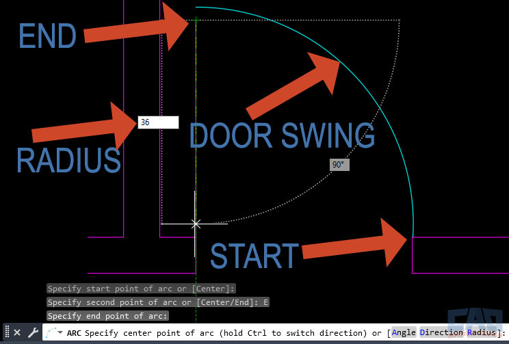
ARC drawn in AutoCAD using Start-End-Radius method with a 36 unit radius.
Example:
- Start point: (0,0)
- End point: (36,0)
- Radius: 36
This creates a semicircle arc above the X-axis.
Advantages:
- You control both span and curvature.
- Perfect for architectural elements like door swings.
Limitations:
- If the chosen radius is too small, AutoCAD won’t generate the arc (error).
4. Step-by-Step: Center–Start–End Method
When you know the center of the circle your arc belongs to, this method is more intuitive.
Steps:
- Start ARC (A + Enter).
- Type C (for center option).
- Pick the center point of the arc.
- Select the start point.
- Select the end point.
Example Use Case:
- Drawing a circular skylight section in an architectural drawing.
- Since the skylight is circular, the center point is known; defining the arc ensures alignment with the circle’s radius.
Advantages:
- Great for geometry tied to a known center.
- Works seamlessly when drafting mechanical parts with circular references.
5. Real-World Example: Door Swing in Architectural Drafting
Consider a 36-inch wide door:
- Place the hinge point.
- Run the ARC command → Start–End–Radius.
- Use the hinge as start point, jamb location as end point.
- Enter 36 as radius.
The resulting arc perfectly represents the door’s swing.

AutoCAD door swing drawn with ARC command radius method.
This method ensures code compliance (door clearance), improves readability, and eliminates errors in construction documents.
6. Common Mistakes and How to Avoid Them
- Wrong Arc Direction
- Sometimes the arc curves the “wrong way.”
- Fix: Reverse the order of start/end points, or use grip editing to flip it.
- Invalid Radius Error
- AutoCAD may return: “Radius too small for given points.”
- Fix: Either increase radius or move points further apart.
- Unit Mismatch
- If you’re working in inches but expect meters, your arcs may look wrong.
- Fix: Confirm drawing units (UNITS command).
- Over-reliance on eyeballing
- Placing arcs without snaps can lead to geometry drift.
- Fix: Always use OSNAPs (endpoints, midpoints, intersections).
7. Tips for Efficiency
- Dynamic Input (F12)
- Shows radius value live as you draw. Useful for visual verification.
- Object Snaps (F3)
- Lock onto exact points (e.g., circle centers, line intersections) for accuracy.
- FILLET Command Alternative
- Need a tangent arc between two objects? Use FILLET with a set radius instead of drawing an independent arc.
- Grip Editing
- Once placed, you can stretch, flip, or extend arcs via grips. Right-click a grip for extra options.
- Block Templates
- If you use fixed arcs often (like door swings), create reusable blocks with parameterized radii.
8. Comparing Radius vs Other ARC Methods
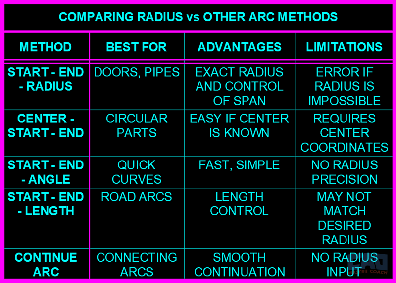
Here’s how radius-based arcs stack up:
| Method | Best For | Advantages | Limitations |
|---|---|---|---|
|
Start-End-Radius |
Doors, Pipes | Exact Radius and Control of Span | Error if Radius is Impossible |
| Center-Start-End | Circular Parts | Easy if Center is known | Requires Center coordinates |
| Start-End-Angle | Quick Curves | Fast, Simple | No Radius Precision |
| Start-End-Length | Road Arcs | Length Control | May Not Match Desired Radius |
| Continue ARC | Connecting Arcs | Smooth Continuation | No Radius Input |
Prefer a visual guide? Here’s the same comparison as a quick-reference chart.

Comparison of AutoCAD ARC methods: radius, angle, length, and center options.
9. Advanced Applications
- Structural Engineering
- Curved steel beams and arches in stadium design require precise radii for fabrication.
- Mechanical Drafting
- Gear teeth often rely on arcs of specific radii to mesh properly.
- Landscape Architecture
- Walkways and fountains frequently include repeated arcs of identical radii for aesthetics and flow.
- Civil Engineering
- Road curves are designed based on radius for vehicle safety (minimum curve radius depends on speed).
10. Troubleshooting Workflow
- If an arc won’t form, double-check:
- Are your points too close?
- Did you input a radius larger than possible?
- Are you working in the right unit system?
- Use PROPERTIES palette to check and adjust radius after creation.
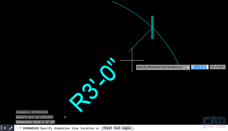
- Use DIMRADIUS to confirm the actual radius of drawn arcs.

AutoCAD ARC with radius dimension annotation using DIMRADIUS command.
Conclusion
Drawing arcs by radius in AutoCAD is one of the most powerful drafting techniques for precision, code compliance, and real-world accuracy. Whether you’re an architect, engineer, or designer, mastering this method ensures your drawings are professional, consistent, and error-free.
Practice both the Start–End–Radius and Center–Start–End methods until they become second nature. Combine them with OSNAPs, dynamic input, and layering strategies, and you’ll elevate your drafting speed and accuracy significantly.


