AutoCAD LINE vs POLYLINE Explained: Differences, Examples, and Best Practices
Introduction
AutoCAD offers more than one way to draw connected segments. At first glance, the LINE and POLYLINE commands seem similar: both can create connected geometry, both appear as straight segments, and both can form shapes. But there are critical differences that affect editing, hatching, dimensioning, and plotting.
Understanding when to use LINE vs POLYLINE will make your drawings cleaner, easier to edit, and more professional. In this article, we’ll break down the differences, explore practical use cases, and share best practices. By the end, you’ll know exactly when to reach for each tool.
1. What is a LINE in AutoCAD?
In AutoCAD, the LINE command is one of the most fundamental drawing tools, and for many users, it’s the very first command they ever learn. A line is exactly what it sounds like: a straight segment drawn between two points that you specify. While it looks simple, it is the foundation of most technical drawings. The important detail to understand is that each line you draw is an independent object. Even if you draw five connected segments one after another in the same command, AutoCAD will treat each one as a separate line object.
This independence has both advantages and disadvantages. On the positive side, individual lines give you precise control over each segment. You can move, stretch, trim, or delete one line without affecting the others. For quick drafting tasks, this can be very efficient. For example, when sketching the outline of a new room layout, you might throw down a few lines to get an idea of wall placements without worrying about connections or closed shapes. Lines are also great for temporary construction geometry — reference marks, guidelines, or quick layout checks — because they’re fast to place and just as easy to erase.

AutoCAD LINE segment with grips selected.
However, this independence can also cause problems when you need those segments to behave as one object. If you try to hatch an area made up of separate lines, even tiny gaps between them can cause the hatch to leak out or fail altogether. Editing can also become tedious. Imagine trying to lengthen a boundary made of twenty separate line segments; each one must be adjusted individually. In larger drawings, this creates clutter in your selection set, making the file harder to manage.
For these reasons, the LINE command is best used when you’re drawing isolated segments that do not logically belong to a larger shape or when you need quick, disposable geometry. It’s a great tool for sketching, construction lines, centerlines, or details that don’t need to be joined together. Understanding its limitations prepares you for when a POLYLINE might be the better choice.
Key properties of LINEs:
- Each segment is independent.
- Easy to create quickly.
- Ideal for geometry that doesn’t need to behave as one unit.
Example Uses:
- A quick construction line.
- Drawing gridlines or reference geometry.
- Isolated detail elements that won’t be joined.
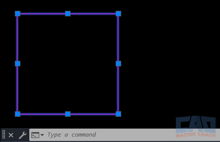
AutoCAD shape made of individual lines instead of a polyline.
2. What is a POLYLINE in AutoCAD?
The POLYLINE command (often shortened to PLINE) takes the concept of a line and expands it into something far more powerful. Unlike the LINE command, which creates individual segments, a polyline allows you to draw a series of connected segments that together form a single object. This means AutoCAD treats the entire path as one entity, no matter how many corners, straight segments, or arcs it contains.
A polyline can do everything a simple line can, but with additional features that make it especially valuable in technical drawings. For instance, a polyline can include both straight and curved sections, letting you draft complex shapes without breaking them into multiple pieces. You can also assign variable widths to a polyline, meaning the line can start thick and taper to thin or maintain a consistent width throughout. This is particularly useful for showing roads in civil plans, centerlines in mechanical parts, or piping runs in MEP drawings. Because all the segments are bound together, they move and edit as a unit. A single selection lets you stretch, offset, fillet, or apply grips across the entire shape, saving huge amounts of time compared to editing dozens of individual lines.
Polylines also shine when it comes to creating closed shapes. A closed polyline can be instantly hatched, extruded into a 3D solid, or converted into a region. This makes it indispensable for floor plan perimeters, property boundaries, or any shape that will be filled or calculated later. A closed polyline is mathematically reliable — there are no microscopic gaps to worry about.
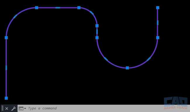
AutoCAD polyline with arcs and straight lines as one object.
While polylines may take slightly longer to create upfront, they pay off in efficiency and accuracy throughout the drafting process. They keep drawings cleaner, file sizes smaller, and editing more predictable. In short: whenever you’re drawing something that represents a logical, connected object, especially one that will be hatched, dimensioned, or extruded, a polyline is almost always the right choice.
Key properties of POLYLINEs:
- All connected segments behave as one object.
- Can include both arcs and straight lines.
- Supports widths (tapered lines).
- Can be converted into regions or used for hatching more reliably.
Example Uses:
- Floor plan outlines (continuous perimeter).
- Property boundaries.
- Paths, roads, or utility layouts.
3. Key Differences Between LINE and POLYLINE
At first glance, the LINE and POLYLINE commands can seem interchangeable. Both allow you to create straight segments, both can connect from one point to the next, and both are part of nearly every AutoCAD drawing. It’s common for beginners to assume that it doesn’t matter which tool they use — after all, a wall drawn with four lines looks just like a wall drawn with one closed polyline. But the differences go much deeper and understanding them will save you headaches later.
The most important distinction is how AutoCAD treats the geometry you create. A set of lines is just that: multiple, separate objects. Each segment can be selected, modified, or deleted on its own. By contrast, a polyline binds all its segments into one continuous object. You don’t just have four lines that happen to touch at their endpoints — you have a single object with four vertices. This difference changes how editing, hatching, dimensioning, and even file performance behaves.
Take editing as an example. Imagine you’re drawing the perimeter of a room. If you draft it using four separate lines, stretching one wall outward means adjusting at least two segments, and it’s easy to miss a tiny gap at a corner. With a polyline, you grab one grip, stretch it, and the entire boundary updates instantly. The time savings add up quickly when you’re working on larger projects with dozens or even hundreds of shapes.
Another key difference is in how AutoCAD understands continuity. A set of lines may appear closed, but to the program they’re just four independent edges. That matters when you try to hatch the inside of a shape or extrude it into 3D. Even a microscopic gap between line endpoints can cause the hatch to “leak” out of the shape or fail altogether. A closed polyline, on the other hand, is mathematically watertight. AutoCAD knows it’s a single closed loop, so hatches, fills, and extrusions work without surprises.
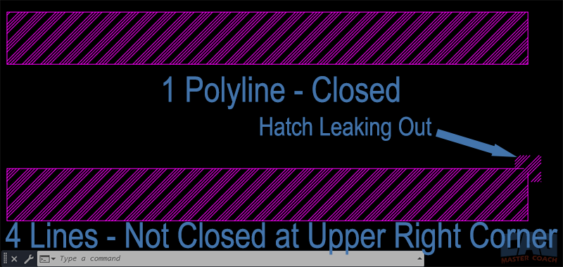
AutoCAD hatch comparison: line segments vs closed polyline.
Polylines also unlock features that lines simply don’t have. You can assign widths to make a polyline thicker at one end and thinner at the other, which is useful for things like roadway centerlines or schematic diagrams. You can even mix arcs and straight segments in the same polyline, letting you create complex profiles without switching commands.
So, while lines are great for speed and independence, polylines provide control, efficiency, and reliability. The table below highlights these differences side by side so you can quickly compare their properties and decide which one is right for your drawing.
|
Feature |
LINE | POLYLINE |
|---|---|---|
| Object Type | Each segment is a seperate object | All segments are part of one object |
| Editing | Edit each line individually | Grip-edit entire polyline as one |
| Curves | Only straight segments | Can include arcs + straight segments |
| Width | Always single thickness | Can set variable widths |
| Hatching | Gaps between lines may cause hatch leaks or no hatch creation | Polylines hatch cleanly as closed lines |
| File SIze | Slightly lighter of many short lines | Efficient for complex shapes (fewer objects) |
| Conversion | Can join with PEDIT | Can EXPLODE into seperate lines |
4. Practical Examples
Sometimes the best way to understand the difference between lines and polylines is to see how professionals in different fields apply them in real projects. Let’s look at three disciplines — architecture, civil engineering, and mechanical drafting — where the choice between the two commands can make a noticeable impact.
Architecture: Floor Plans and Details
Architects rely heavily on polylines when defining building footprints and room boundaries. Imagine drafting a simple floor plan: the exterior walls form a continuous perimeter, with door and window openings cut into them. If this boundary were drawn with individual lines, even the slightest misalignment could prevent the drawing from hatching correctly or cause errors later when generating construction documents. By using a closed polyline, the architect ensures the boundary is watertight. When it comes time to hatch in wall fills or calculate areas, the closed polyline behaves exactly as needed.
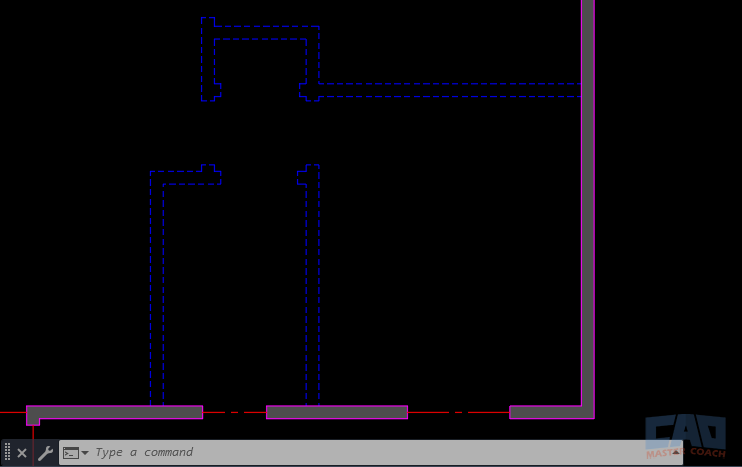
AutoCAD floor plan example using polyline perimeter and line partitions.
That said, not everything in an architectural drawing will benefit from polylines. Interior partition walls, for example, may be drawn as simple lines. These are often adjusted frequently in early design phases and keeping them as independent line objects allows the drafter to nudge, stretch, or delete them quickly without affecting the larger drawing. Similarly, temporary layout lines or reference geometry — like furniture outlines or alignment guides — are often created with the LINE command since they are disposable and don’t need to be connected.
Civil Engineering: Boundaries and Infrastructure
In civil drawings, the distinction becomes even more critical. Property boundaries are a prime example where polylines shine. Survey bearings and distances are usually plotted as connected segments, and a closed polyline ensures the parcel can be easily labeled, dimensioned, or hatched. If the boundary were drawn with lines, joining and editing would be tedious, and any hatch or area calculation could fail due to small gaps at vertices.
Polylines are also common for infrastructure features such as roadway centerlines, sidewalks, and utility paths. A single polyline representing a road alignment allows engineers to offset it for lane edges, adjust curves, and generate profiles. If this were drawn with separate lines and arcs, editing the alignment would be much more cumbersome.
On the other hand, construction staking lines or temporary grading guides might still be created with individual lines, especially when they’re used for one-off checks or quick design iterations. Civil engineers often draft with both tools in the same drawing, choosing whichever provides the right balance of accuracy and flexibility.
Mechanical Drafting: Profiles and Reference Geometry
Mechanical designers often need geometry that can be extruded or revolved into 3D parts. For this, polylines are essential. Consider drafting a profile of a machine bracket to be extruded into a solid. A single closed polyline guarantees the shape is continuous and can be used directly for 3D modeling. If the profile were drafted with separate lines, it would need to be painstakingly joined together before extrusion, which wastes time and introduces room for error.
Still, there are places where plain lines are preferable in mechanical drawings. Quick reference geometry, like centerlines, axes, or construction guides, are often left as individual lines. These are not part of the final manufactured object and benefit from being easily manipulated or erased without affecting other geometry.
Takeaway
Across all three disciplines, the pattern is consistent: lines are best for quick, disposable, or independent geometry, while polylines are best for anything that represents a continuous object or boundary. By understanding how each tool supports the workflow of architects, engineers, and designers, you’ll be able to make smarter choices in your own drafting.
5. Editing: Grip Control and Commands
The real test of whether you should use a LINE or a POLYLINE often comes when it’s time to edit your drawing. Creating geometry is only the first step; as a project develops, you’ll need to stretch, offset, or reshape objects. This is where the editing behavior of lines versus polylines really shows its differences.
Editing with Lines
When you select a line in AutoCAD, you’ll notice it highlights individually, with one grip at each endpoint and one in the middle. If you’ve drawn a square with four line segments, selecting one side only highlights that side. To stretch a corner outward, you would need to select and edit at least two lines. If the shape has many segments, this becomes repetitive and introduces room for error, especially if the endpoints don’t remain perfectly joined.
For example, say you have a rectangular room drafted from four lines. If you stretch one wall outward, you must remember to adjust the adjacent walls too, and double-check that no gaps appear at the corners. Small misalignments may not be obvious on screen but can ruin hatching or dimensioning later. In large projects, this extra management quickly adds up.
Editing with Polylines
Polylines, by contrast, behave as a single object. Select one segment of a polyline and the entire chain highlights, no matter how many corners or curves it has. Grips appear at each vertex, letting you stretch or move corners individually while keeping the rest of the object intact. If you move one corner of a rectangular polyline, the other sides stay connected, so the shape never breaks apart.
Polylines also have mid-segment grips. With these, you can quickly add a new vertex, convert a straight segment into an arc, or reshape the object without redrawing. This flexibility makes polylines ideal for iterative design where shapes need frequent adjustments.
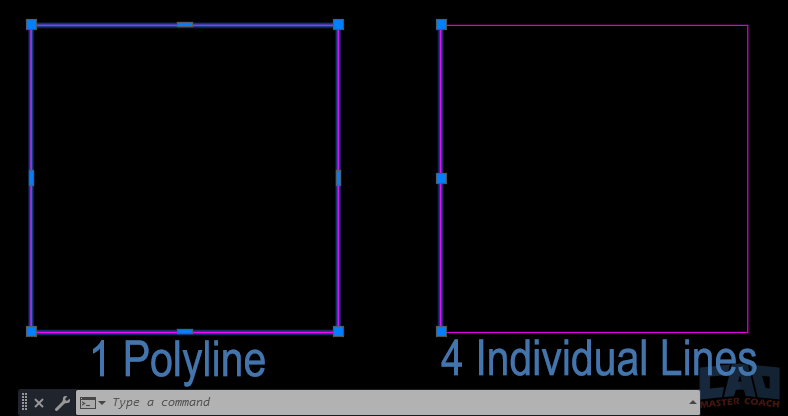
AutoCAD editing comparison: grips on polyline versus individual lines.
Commands That Enhance Editing
- PEDIT (Polyline Edit): This is the command that unlocks even more power. With PEDIT, you can convert ordinary lines into polylines, join multiple lines into one continuous object, add arcs, or change widths. For example, if you start by sketching walls with lines, you can later join them into a polyline for easier editing and hatching.
- JOIN: A simpler way to combine lines into polylines. It works best when the lines meet exactly at their endpoints.
- EXPLODE: Sometimes you’ll want to go in the opposite direction — breaking a polyline into its individual line and arc segments. EXPLODE is useful if you need to isolate a segment for unique editing. Be careful, though; once exploded, you lose the benefits of having a single object.
The Editing Advantage
The bottom line: editing with polylines is almost always more efficient and reliable. Instead of juggling dozens of separate segments, you can manipulate an entire object in one move. While lines still have their place for quick geometry, once your drawing reaches the refinement stage, polylines will save you significant time and prevent drafting errors.
6. Best Practices: Which Should You Use?
Choosing between the LINE and POLYLINE commands isn’t always black and white. Both tools are valuable, and skilled drafters know how to use each one in the right context. The key is to think ahead: ask yourself how the geometry will be used later in the project. Will it be part of a continuous boundary, or is it just a quick reference? Will it need to be hatched, dimensioned, or extruded? By considering these questions up front, you’ll save yourself hours of cleanup later.
When to Use LINES
Use the LINE command when speed and independence are your priorities. For quick sketches, construction geometry, or elements that won’t interact with hatching or area calculations, lines are the simplest choice. For instance:
- Construction Lines: Temporary guides that help you align other objects.
- Partitions or Details: Interior walls that may be moved frequently during design.
- Reference Marks: Axes, centerlines, or other drafting aids that won’t appear in the final plotted drawing.
Lines are also useful when precision at the object level isn’t as important — for example, when you’re still experimenting with a layout. Since each segment is independent, you can delete or adjust one without affecting the others.
When to Use POLYLINES
Polylines are the better choice whenever your geometry represents a single logical object. Examples include:
- Closed Boundaries: Floor plan perimeters, property lines, or hatch regions.
- Profiles for 3D Modeling: Shapes intended for extrusion or revolution.
- Infrastructure Paths: Roads, utility runs, or site features that need offsets.
- Design Iterations: Shapes you know will require stretching, offsetting, or frequent edits.
Because polylines behave as one object, they’re cleaner and more predictable in downstream tasks like hatching, dimensioning, or exporting to other software.
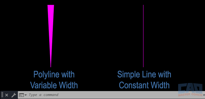
AutoCAD polyline example showing variable line width.
Common Pitfalls to Avoid
- Mixing Lines and Polylines: If half your shape is made of lines and the other half of a polyline, hatches and edits can fail. Keep objects consistent.
- Forgetting to Close Polylines: A polyline that isn’t closed won’t hatch properly. Always check the “Close” option or confirm the last vertex connects back to the start.
- Overusing Explode: While EXPLODE can be helpful, overusing it defeats the purpose of polylines and clutters your drawing. Explode only when absolutely necessary.
Following this guideline will keep your drawings cleaner, your edits faster, and your downstream tasks more reliable.


