AutoCAD LINE Command Basics: Draw Straight, Angled, and Precise Lines
Introduction
The LINE command is the very first tool most AutoCAD users learn — and for good reason. Nearly everything in AutoCAD is built from lines. Whether you’re sketching the outline of a house, laying out a site boundary, or setting up the axis for a mechanical component, lines are the foundation of drafting.
At first glance, drawing a line seems simple: click once to start, click again to finish. But AutoCAD gives you far more control than just “point and click.” You can specify exact lengths, angles, and coordinates, use tools like Ortho Mode, Polar Tracking, and Dynamic Input, and build accurate frameworks for complex designs.
In this guide, we’ll take a step-by-step look at the LINE command, expanding beyond the basics into practical techniques that make your drawings accurate, efficient, and professional. By the end, you’ll know how to:
- Start the LINE command in different ways.
- Use absolute and relative coordinates for precision.
- Draw lines at exact lengths and angles.
- Apply Ortho mode, Polar Tracking, and Dynamic Input.
- Chain multiple lines together to form shapes.
- Avoid common mistakes that beginners often make.
This article also links to three additional guides: Line vs. Polyline, Editing Lines in AutoCAD, and Best Practices with Lines. Together, they form a complete cluster on one of AutoCAD’s most essential commands.
1. Starting the LINE Command
There are multiple ways to launch the LINE command, and learning each method will save you clicks in different situations.
- Ribbon Method: Go to the Home tab → Draw panel → Line tool. Great for beginners because it’s visual and easy to find.
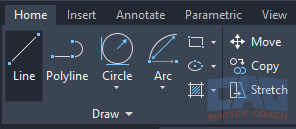
AutoCAD LINE command button in the ribbon Draw panel.
- Command Line: Type LINE or the shortcut L and hit Enter. This is the fastest method once you’re comfortable with AutoCAD’s text-based input.
- Classic Toolbar/Icons: In the “Classic” workspace, the LINE icon is right in the Draw toolbar.
- Shortcut Menus: Right-clicking in the drawing area often reveals “Line” in the quick menu.
Steps:
- After starting the command, AutoCAD prompts:
- Specify first point:
- You can either click a location on screen or type exact coordinates — more on that next.
2. Entering Coordinates: Absolute and Relative
Coordinates are what make AutoCAD drawings precise. Instead of “eyeballing” where a line goes, you tell AutoCAD exactly where to place it.
- Absolute Coordinates: Points are referenced from the drawing’s origin (0,0).
- Example: Typing 10,5 places a point 10 units right and 5 units up from the origin.
- Relative Coordinates: Points are referenced from the last point you placed. Precede them with @.
- Example: Typing @5,0 draws a line 5 units long horizontally from the last point.
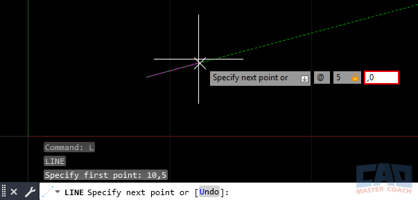
Absolute vs. relative coordinates in AutoCAD LINE command.
Practical Example: House Floor Plan
- First wall: Start at 0,0.
- Second wall: Type @20,0 to draw a 20-foot-long wall.
- Third wall: Type @0,15 to go up 15 feet.
- Continue around until the shape is closed.
This way, you don’t guess or drag the mouse — you define your building’s footprint with exact numbers.
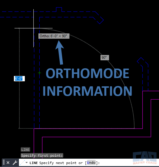
Using AutoCAD LINE command with Ortho and relative input for floor plans.
3. Ortho Mode: Perfectly Straight Lines
When you need perfectly vertical or horizontal lines, turn on Ortho Mode by pressing F8. With Ortho active, every line you draw is locked to exactly 0°, 90°, 180°, or 270°.
- Architecture Example: Drawing exterior walls of a house. Ortho ensures they’re square.
- Engineering Example: Laying out a bolt pattern grid. Ortho guarantees all axes align perfectly.
Without Ortho, it’s easy to accidentally draw a line at 89.9° instead of 90°, which can cause huge headaches when dimensioning or aligning geometry later.
4. Drawing Lines at Angles and Lengths
AutoCAD shines when you need precision at specific angles. Use the format:
- @Length<Angle>
- @10<45 = a line 10 units long at 45°.
- @25<180 = a line 25 units long going left.
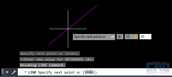
Drawing angled lines with AutoCAD LINE command using @length<angle.
By default, angles are measured counterclockwise from the positive X-axis (to the right). If you need bearings or custom angle settings, adjust them in the UNITS dialog.
Practical Example: Property Survey
Say you’re entering a deed description:
- First side: @100<0 → 100 feet east.
- Second side: @75<90 → 75 feet north.
- Third side: @100<180 → 100 feet west.
- Fourth side: @75<270 → 75 feet south (closing the rectangle).
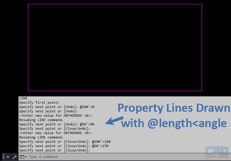
Using AutoCAD LINE command to draw property boundaries with bearings.
This replicates a property lot exactly as surveyed.
5. Polar Tracking: Guided Angles
If you don’t want to memorize or type angle values, Polar Tracking helps. Toggle with F10.
When Polar is on, AutoCAD shows a temporary guide whenever your cursor approaches preset angles (like 30°, 45°, or 90°).
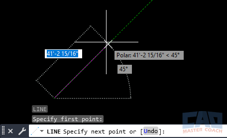
Drawing angled lines with AutoCAD polar tracking.
- Move your cursor near 45°.
- Type 12 and press Enter.
- AutoCAD draws a 12-unit line at exactly 45°.
Example: Mechanical Drafting
When sketching the chamfer of a part, you may need a 30° line. With Polar Tracking set to 30°, just move the mouse and type the distance — quick and accurate.
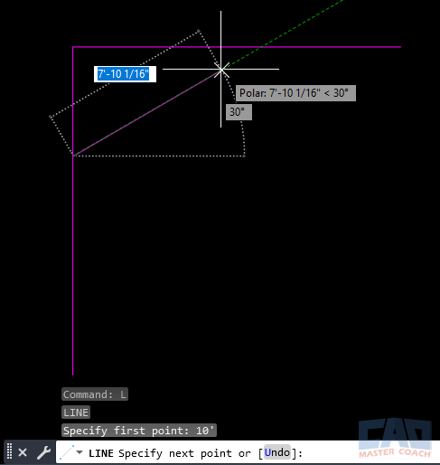
AutoCAD polar tracking example creating chamfer lines.
6. Dynamic Input: On-Screen Precision
Dynamic Input (toggle with F12) lets you type distances and angles right next to the cursor instead of looking at the command line.
- Click to start.
- Move the mouse in the general direction.
- Type the length, press Tab, then type the angle.
- Hit Enter — the line is drawn.
This feature keeps your focus in the drawing window and is popular with beginners.
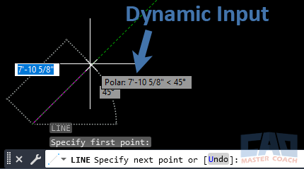
Using AutoCAD Dynamic Input for line length and angle entry.
Example: Site Plan Layout
You’re drawing a parking lot boundary: start at a corner, move cursor northeast, type 50 (feet), press Tab, type 30°. Instantly you have a precise angled edge.
7. Chaining Multiple Lines Together
When drawing with the LINE command, each click or input adds another segment. You can keep going until you press ENTER or ESC.
- To close a shape quickly, type C at the prompt.
- AutoCAD connects the last point back to the first with a final line.
This chaining is great for rough shapes, but remember: LINE creates separate segments, while Polyline (PLINE) creates one continuous object (see Line vs. Polyline).
8. Practical Applications Across Industries
Architecture
- Floor plans: drawing exterior and interior walls with Ortho.
- Roof slopes: angled lines at 30° or 45° for gables.
Civil Engineering
- Site boundaries: entering deed calls with length/angle format.
- Road alignments: drawing tangent segments before arcs.
Mechanical Design
- Part sketches: angled lines for chamfers and tapers.
- Symmetry setups: axes and construction lines.
Construction Detailing
- Sections: baseline horizontal/vertical lines.
- Elevations: sloped rooflines and angled braces.
No matter your discipline, the LINE command is the first step toward accurate construction documents.
9. Common Mistakes Beginners Make
- Skewed Lines: Forgetting Ortho, drawing at 89.9° instead of 90°.
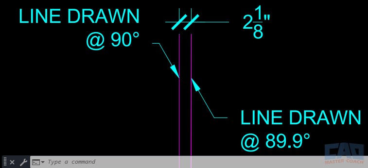
Common AutoCAD LINE command mistake: skewed lines vs. Ortho.
The two lines in the image above are 100’ long and have the same starting point. By drawing one of the lines one-tenth of one degree off from the correct angle, in 100 feet the is off by 2.125 inches. Using Ortho Mode can eliminate this mistake.
- Wrong Coordinate Mode: Typing 10,5 when you meant @10,5.
- Angle Direction Confusion: Entering clockwise instead of counterclockwise.
- Ignoring Units: Forgetting whether lengths are in feet, inches, or millimeters.
Solution: Practice toggling Ortho (F8), Polar Tracking (F10), and Dynamic Input (F12) until they become second nature.
10. Quick Reference Table
Sometimes you just need a quick reminder of the right input format or shortcut without reading through a full tutorial. The table below serves as a handy reference for the most common ways to use the LINE command — from starting the tool, entering coordinates, and specifying angles, to toggling Ortho, Polar Tracking, and Dynamic Input.
|
Task |
Shortcut/Method |
Example |
|
Start LINE Command |
L + Enter |
– |
|
Absolute Coordinate |
X,Y |
10,5 |
|
Relative Coordinate |
@X,Y |
@5,0 |
|
Length + Angle |
@Length<Angle> |
@10<45 |
|
Ortho Mode |
F8 |
Horizontal/vertical lines |
|
Polar Tracking |
F10 |
Snap guide at 45° |
|
Dynamic Input |
F12 |
Enter on-screen |
|
Close Shape |
Type C |
Closes back to start |
If you’d like a visual version of this quick reference, we’ve also included a downloadable graphic. You can use the table above for detail or grab the graphic for a simpler at-a-glance guide.
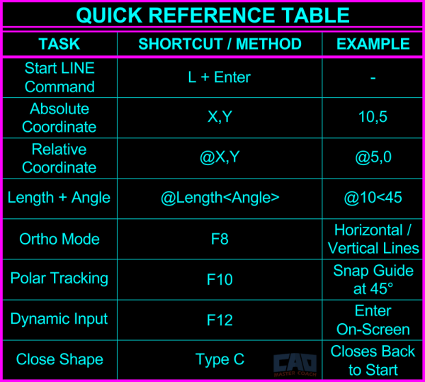
Quick reference guide for AutoCAD LINE command inputs.
11. Frequently Asked Questions (FAQs)
New AutoCAD users often run into the same questions when learning the LINE command. Below are clear answers to the most common ones, so you don’t have to dig through menus or guess at the right input.
Turn on Ortho Mode (F8), pick your first point, move the cursor vertically, and type the length.
Use the @Length<Angle> format. For example, @10<45 draws a 10-unit line at 45°.
A line (LINE) is a single segment. If you draw multiple lines, each is a separate object. A polyline (PLINE) creates one continuous object, which is often easier to edit.
Use absolute coordinates (10,5) for points measured from the origin, or relative coordinates (@5,0) for points measured from your last point.
Type C at the prompt, and AutoCAD will connect the last point back to the first with a final segment.
Ortho Mode may be off, or Polar Tracking isn’t aligned with your intended angle. Toggle F8 or F10 to fix it.
Use the UNITS command to switch between degrees, grads, or surveyor’s bearings.
Yes. Start the line, move the cursor in the right direction, then type the length directly. Combine with Ortho or Polar Tracking for accuracy.
Use the LENGTHEN command or grip-edit the endpoint. For more editing tips, see Editing Lines in AutoCAD.
Keep geometry straight with Ortho/Polar, avoid overlaps and gaps, and use layers consistently. For more guidance, see Best Practices with Lines.
