Editing Lines in AutoCAD – TRIM, EXTEND, STRETCH, and More
Introduction
The LINE command is one of the most fundamental tools in AutoCAD. But drawing lines is only half the story—real productivity comes from editing them. Whether you are adjusting endpoints, trimming overlaps, joining segments, or moving an entire design element, knowing how to edit lines quickly and accurately saves time and ensures your drawings are precise.
In this guide, we’ll explore the most important ways to edit lines in AutoCAD, walking through each technique step-by-step. By the end, you’ll have a toolbox of editing methods that will make you faster, more accurate, and more confident in your drawings.
1. Why Editing Lines Matters
Lines form the backbone of nearly every drawing, from architectural floor plans to mechanical assemblies. Even if you start with carefully measured inputs, design is iterative—lines often need adjustment. Editing lines efficiently means you can refine designs without starting over, keep drawings clean, and maintain professional standards.
Some common reasons to edit lines include:
- Correcting mistakes or mis-clicks
- Adjusting for design changes
- Cleaning up overlapping geometry
- Connecting lines into continuous polylines
- Simplifying complex sketches
2. Basic Editing Tools in AutoCAD
AutoCAD provides several ways to manipulate lines directly. Some are part of the Modify panel, while others are command-line driven.
Commonly Used Line Editing Commands
- MOVE – Relocates a line or group of lines
- ROTATE – Spins a line around a base point
- TRIM – Cuts a line back to a boundary
- EXTEND – Grows a line to meet another object
- LENGTHEN – Changes a line’s length or angle
- STRETCH – Deforms line endpoints while preserving others
- JOIN – Converts separate lines into one continuous object
- BREAK – Splits a line into two parts
Each of these has its own strengths, and we’ll look at them in detail.
3. Grips: The Fastest Way to Edit Lines
Grips are small squares that appear when you select a line. They allow quick, intuitive editing without launching a separate command.
- Endpoint grips let you drag and reposition line ends.
- Midpoint grips allow you to move an entire line segment while maintaining its length.
- Right-clicking a grip opens additional options, such as “Stretch,” “Rotate,” or “Mirror.”
Grips are especially useful for quick adjustments when accuracy is less critical, or when combined with Object Snaps (OSNAP) to ensure precision.
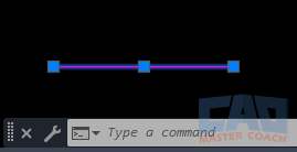
Selecting a line shows endpoint and midpoint grips for quick editing.
4. Using TRIM and EXTEND
TRIM
The TRIM command removes excess portions of a line. You select a cutting edge (boundary) and then click on the part of the line you want to remove.
Example: trimming wall segments so they end neatly at a door opening.
EXTEND
The EXTEND command works like the opposite of TRIM—it lengthens a line until it meets another object.
Example: extending property lines until they intersect at a boundary corner.
Tips:
- Use Shift during TRIM to toggle between trimming and extending without restarting the command.
- Combine TRIM and EXTEND in a single workflow for faster cleanups.
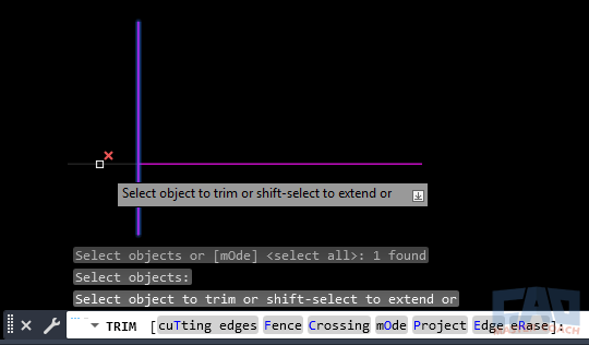
Cleaning up overlapping and short lines with TRIM and EXTEND.
5. STRETCH: Adjusting Multiple Lines
The STRETCH command allows you to lengthen or shorten parts of your drawing by selecting endpoints with a crossing window. Unlike MOVE, it doesn’t relocate the whole object—it only adjusts parts within the selection.
This is especially powerful when modifying layouts like walls or piping systems, where multiple lines must remain aligned while changing length.
Steps:
- Type STRETCH or use the ribbon.
- Create a crossing window (drag from right to left) around the endpoints you want to adjust.
- Specify a base point and new location.
6. LENGTHEN: Fine-Tuning Line Length
The LENGTHEN command is one of the most precise ways to adjust a line in AutoCAD. Unlike TRIM, EXTEND, or STRETCH (which often rely on other geometry or windows), LENGTHEN gives you direct control over exactly how much to change.
When you start the command, you can choose from four methods:
- Total length – Specify the exact new total length of the line.
- Delta – Add or subtract a given distance from the current length.
- Percent – Scale the line length proportionally.
- Dynamic – Drag the endpoint interactively while still reading the updated length on screen.
7. BREAK and JOIN: Splitting and Combining
BREAK
The BREAK command is used when you need to divide a single line into two separate objects. This can be useful for:
- Creating an opening in a wall representation.
- Splitting a centerline so that dimensions or annotations don’t overlap it.
- Removing an unwanted segment in the middle of a line.
There are two main approaches:
- Single break point – AutoCAD uses the same location for the start and end of the break, creating a visible gap.
- Two break points – Select both ends of the segment you want to remove, leaving two separate line objects on either side.
One common mistake is assuming BREAK deletes the entire line between two objects—it doesn’t. AutoCAD creates two separate line objects behind, which may later need to be joined.
JOIN
The JOIN command works in the opposite direction, merging multiple lines (and sometimes arcs or polylines) into a single continuous polyline.
Why JOIN matters:
- The HATCH command requires closed boundaries.
- Joined lines are easier to select as one object instead of managing multiple pieces.
- Clean geometry helps avoid overlapping linework that causes plotting or modeling errors.
Workflow Example: If you draft the outline of a mechanical bracket with four separate lines, AutoCAD treats them as individual objects. Using JOIN, you can combine them into a single closed polyline, making it easier to offset for material thickness or hatch for section views.

Splitting a line into two or combining multiple lines into one.
8. Rotate, Move, and Mirror
These three commands may seem basic, but they are essential in editing lines after you’ve drawn them.
ROTATE
The ROTATE command allows you to spin a line around a base point. This is crucial when aligning geometry with angled features or when correcting drafting mistakes. For example, you can take a mis-aligned roof slope line and rotate it by 7° around the building corner to match design intent.
MOVE
The MOVE command is the most straightforward editing action—relocating a line from one spot to another. However, the power of MOVE lies in using Object Snaps (OSNAP) to place lines precisely. Instead of dragging freely, always base your movement on reference points such as midpoints, endpoints, or intersections.
MIRROR
The MIRROR command duplicates and flips a line across a defined axis. It’s often used in symmetrical drawings such as floor plans, machine parts, or structural grids. Instead of redrawing the other half, you can mirror existing geometry across a centerline.
9. Converting Lines to Polylines
Sometimes, a set of disconnected line segments makes editing inefficient. AutoCAD offers a way to convert them into a polyline (a single, continuous object) using the PEDIT (Polyline Edit) command.
Benefits of Polylines:
- Single Object Control – Instead of selecting multiple line segments, you only need to click once.
- Advanced Editing – Polylines allow you to add arc segments, change width, or use fit/spline options.
- Better for Modeling – Many 3D and hatch commands require polylines, not simple lines.
- Cleaner Drawings – Fewer gaps and overlaps improve both readability and plotting.
How to Convert a LINE to a POLYLINE:
- Type PEDIT in the command line.
- Select one of the lines.
- AutoCAD asks if you want to convert the line into a polyline — choose Yes.
- Use the JOIN option to add other adjacent lines into the same polyline.
Example: You’ve drawn a rectangle using four separate LINE commands. If you want to hatch the shape, AutoCAD may reject it due to tiny gaps. By converting each segment into a polyline and joining them, you get a clean closed boundary ready for hatching or extrusion.
10. Advanced Workflows
Editing lines doesn’t happen in isolation — professionals use a combination of settings and modes to speed up their work.
Object Snaps (OSNAP)
Always keep OSNAP enabled to “snap” edits to precise locations. Endpoints, midpoints, intersections, and perpendicular snaps guarantee accuracy. Without them, grips and free dragging can introduce small but significant errors.
Ortho Mode
Turn on Ortho (F8) to constrain edits to vertical or horizontal directions. This is especially useful in architectural drawings where walls and grids are typically orthogonal.
Polar Tracking
For angled drawings, use Polar Tracking to lock movements to preset angles like 30°, 45°, or 60°.
Constraints
AutoCAD allows applying geometric constraints (parallel, perpendicular, tangent) and dimensional constraints (exact lengths or angles). This transforms static lines into parametric objects, making future edits even easier.
Dynamic Input
Enable Dynamic Input (F12) to type values directly at the cursor instead of the command line. This keeps your focus in the drawing window and reduces errors.
Workflow Example: Imagine adjusting a stair detail: with Ortho Mode, Polar Tracking, and Object Snaps active, you can quickly trim, extend, and stretch lines while keeping everything aligned and dimensionally correct.
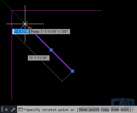
Ensuring accuracy while stretching and aligning lines.
11. Common Mistakes to Avoid
Even experienced users make mistakes when editing lines. Recognizing these pitfalls helps keep your drawings clean and professional.
- Overlapping Lines: Failing to trim excess geometry often leaves multiple lines stacked on top of each other. This leads to double plotting, unexpected hatches, and heavier file sizes.
- Tiny Gaps: Leaving a 0.001” gap between endpoints can break closed boundaries, causing commands like HATCH or OFFSET to fail. Use Object Snaps or JOIN to eliminate gaps.
- Excessive Exploding: Exploding polylines into individual lines may seem like a quick fix, but it creates messy drawings. Whenever possible, keep geometry as polylines.
- Ignoring Precision: Dragging grips without snaps often results in slightly skewed geometry. Always verify with dimensions or snaps.
- Not Cleaning Up After Edits: After a heavy round of TRIM and EXTEND, it’s common to leave stray fragments or short slivers. Use the OVERKILL command to delete duplicates and simplify.
12. Practical Applications
Editing lines is at the core of countless disciplines. Here’s how different fields put these techniques to use:
Architecture
- Adjusting wall centerlines to align with window and door openings.
- Stretching room layouts when design changes increase dimensions.
- Breaking lines for door swings or stair details.
Mechanical Engineering
- Rotating bolt circle lines around a shaft center.
- Joining multiple lines into polylines before extruding a profile.
- Lengthening part outlines to match manufacturing tolerances.
Civil Engineering
- Extending roadway centerlines to meet intersections.
- Breaking survey lines for easements or property divisions.
- Converting survey sketches into continuous polylines for topographic mapping.
Electrical Design
- Trimming schematic lines to connect cleanly with components.
- Mirroring repeated panel layouts.
- Joining wiring lines into polylines for consistent formatting.
Interior Design
- Stretching furniture layouts while maintaining alignment.
- Using MIRROR to duplicate room setups symmetrically.
- Breaking lines to indicate open floor transitions.
Key Takeaway: Every discipline benefits from editing lines. It’s not just about fixing mistakes—it’s about adapting and refining drawings as designs evolve.
Conclusion
Editing lines is just as important as drawing them. By mastering tools like TRIM, EXTEND, STRETCH, LENGTHEN, BREAK, and JOIN, you can quickly refine drawings without redrawing from scratch. Combine these with grips, object snaps, and polylines, and you’ll have full control over the most fundamental AutoCAD element: the line.
