Polar Tracking (AutoCAD Drafting Aid)
AutoCAD Polar Tracking Command Access
COMMAND LINE: POLAR

DEFAULT KEYBOARD SHORTCUT: F10
STATUS BAR: POLAR TRACKING
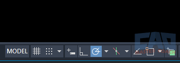
What Is Polar Tracking?
Polar Tracking is one of the most important drafting aids in AutoCAD — and one of the most overlooked. If ORTHO gives you precision by locking you to horizontal and vertical movement, Polar Tracking gives you precision by guiding you along any preset angle you choose.
Think of it as precision without restriction.
When Polar Tracking is turned on, AutoCAD displays a dotted alignment path (and a tooltip) whenever your cursor approaches a defined angle. This allows you to draw at exact angles — 30°, 45°, 60°, 90°, or any additional angles you specify — without ever typing @distance<angle.
If you’ve ever needed to draw a slope line at 2:1, a roof pitch at 4:12, an angled brace at 45°, or a pipe segment at 22.5°, Polar Tracking is the fastest way to do it accurately and consistently.
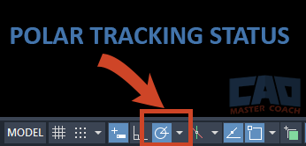
Polar Tracking is controlled from the Status Bar or by pressing F10.
How Polar Tracking Works Behind the Scenes
Even though Polar Tracking feels simple from the user perspective, there’s a lot happening under the hood. AutoCAD is watching for three things:
- Your movement direction
- Whether that direction aligns with one of your defined angles
- Whether you have the correct settings enabled
When all three conditions are met, the cursor “snaps” to a polar alignment path.
You’ll see:
- A dotted line (alignment path)
- A tooltip showing the tracking angle
- A green highlight (theme-dependent) confirming the angle is active
Understanding the Polar Tracking System Variables
Even though most users will never touch these variables directly, knowing what they control helps you understand why Polar Tracking behaves the way it does — and it can make troubleshooting significantly easier. Let's take a deeper look at the Polar Tracking system variables.
POLARANG — Polar Increment Angle
POLARANG controls the primary angle increment for Polar Tracking.
This is the foundation for the angle snap system.
- Default = 90°, which only gives you horizontal and vertical tracking vectors.
- Common engineering values:
- 45° (general drafting)
- 30° (mechanical and piping)
- 15° (fine architectural or mechanical work)
When you change POLARANG, AutoCAD automatically creates tracking vectors at:
- 0°, ±POLARANG
- ±2×POLARANG
- ±3×POLARANG, …
For example:
- If POLARANG = 30°, you get tracking lines at every 30° interval.
- If POLARANG = 15°, you get a dense but flexible set of angles.
Most users will set this once per project type and leave it alone. The increment angle is your “base grid” for angular drafting.
POLARADDANG — Additional Angles
POLARADDANG stores the specific custom angles you type into the Additional Angles box in the Polar Tracking settings.
These are not tied to the increment angle — they act independently.
Typical uses:
- Slope lines (63.4° for 2:1, 71.6° for 3:1, etc.)
- Roof pitches (18.4° for 4:12, 26.6° for 6:12)
- Common bracing angles (30°, 45°, 60°)
- Piping elbows (22.5°, 45°)
You can store multiple angles, and AutoCAD will track to all of them automatically.
Think of the increment angle as your “main grid,” and POLARADDANG as “your personal shortcuts.”
POLARTRACK — Polar Tracking Behavior (Bit-Coded)
POLARTRACK controls how Polar Tracking displays and behaves.
This system variable uses bitcode values, which means each bit in the number turns a specific feature on or off.
You don’t need to memorize the codes, but you should know what they affect:
| Bit Value | Meaning |
|---|---|
| 1 | Enables Polar Tracking |
| 2 | Turns on the tracking tooltip |
| 4 | Controls whether the polar vector is displayed |
| 8 | Allows tracking (acquisition) from OSNAP points |
In other words:
- If POLARTRACK is missing bit 2, you won’t see angle tooltips.
- If it’s missing bit 4, you won’t see the tracking line.
- If it’s missing bit 8, you won’t get polar vectors from OSNAP points.
Most users never modify this variable directly — but seeing tooltips disappear or tracking vectors fail to appear is often caused by an altered POLARTRACK value.
POLARMODE — Interaction With OSNAP Tracking
POLARMODE determines how Polar Tracking interacts with OSNAP Tracking, and whether AutoCAD prioritizes polar angles, snap angles, or both.
This is the variable that determines whether Polar Tracking and OSNAP Tracking “play nicely together.”
Typical behaviors controlled by POLARMODE include:
- Whether polar angles appear when hovering off OSNAP points
- Whether OSNAP tracking vectors override polar vectors
- Whether polar tracking activates from acquired snap points
The default value works for most users, but if polar vectors behave inconsistently — especially when OSNAP Tracking is also turned on — POLARMODE is the first place to look.
Think of it this way:
- POLARTRACK controls what features are visible
- POLARMODE controls how tracking decides which feature wins
Angle Settings — Increment Angles and Additional Angles
Most AutoCAD users don’t realize how customizable Polar Tracking really is.
Increment Angle
This is the main angle AutoCAD will use as the base.
Common engineering choices:
- 30° (mechanical, piping, HVAC)
- 45° (general engineering)
- 15° (detailed architectural or mechanical layouts)
- 90° (the default, but rarely ideal)
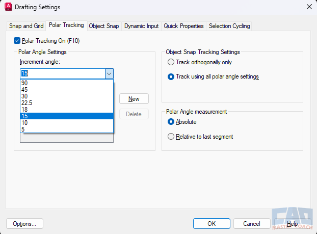
Control angle increments and add custom angles in the Polar Tracking settings window.
Additional Angles
Real-world engineering examples:
| Application | Angle |
|---|---|
| 2:1 slope | 63.4° |
| 3:1 slope | 71.6° |
| 4:1 slope | 75.96° |
| 22.5° elbow (piping) | 22.5° |
| Roof pitch 4:12 | 18.4° |
| Roof pitch 6:12 | 26.6° |
| Bracing / diagonal members | 30°, 45°, 60° |
Adding these into the Additional Angles box saves an enormous amount of time. Instead of typing @12<63.4, you simply hover near 63.4°, watch the angle snap, and type 12.
Using Polar Tracking While Drawing
Once Polar Tracking is on, using it couldn’t be easier:
- Start any command that expects a direction (LINE, RAY, XLINE, MOVE, COPY, ROTATE basepoint, etc.)
- Move your cursor near a defined angle
- When the alignment path appears, type the distance or continue drawing
The key is that Polar Tracking eliminates the need to type the <angle portion of coordinate entry.

The polar alignment path appears when you move your cursor near a defined angle.
Example: Draw a 30° Line, 12 Units Long
Without Polar Tracking:
- @12<30
With Polar Tracking:
- Move cursor near 30°
- Wait for the tracking vector
- Type 12
- Press Enter
It’s that simple.
Combining Polar Tracking with OSNAP
This is where drafting shortcuts really shine.
Workflow:
- Snap to an OSNAP point (Endpoint, Midpoint, Intersection, etc.)
- Move your cursor until the Polar Tracking angle appears
- Type the distance
- Press Enter
This is much faster than typing @distance<angle dozens of times.
Real-World Engineering Examples Using Polar Tracking
One of the biggest advantages of Polar Tracking is that it mirrors the way engineers and designers actually think: angles repeat. Whether you’re working on a site plan, a structural detail, a mechanical system, or an architectural layout, you tend to use the same handful of angles over and over throughout a project. Once you realize that, Polar Tracking becomes one of the most practical and time-saving tools in all of AutoCAD.
Below are real-world examples from different engineering disciplines that show how Polar Tracking becomes less of a “nice feature” and more of a drafting accelerator.
Civil Engineering Examples
Civil drawings rely heavily on angled geometry, and Polar Tracking shines here.
Grading and Slope Lines
When laying out grading, slopes often follow consistent ratios — for example, a 2:1 slope (horizontal:vertical). A 2:1 slope corresponds to 63.4°. Instead of constantly typing @distance<63.4, you can add 63.4° to your Additional Angles and instantly snap to that direction anytime. The same applies for 3:1, 4:1, and even unusual slopes used in retaining structures or drainage channels.
Road Geometrics and Wingwalls
Roadway geometry often includes tangents, angled transitions, flared wingwalls, or drive approach tie-ins. Many engineers like to set their increment angle to 15° because it gives a flexible drafting grid without being overly cluttered. With a 15° increment, you can quickly align retaining walls, align curb returns, or lay out drainage channels at consistent angles that match the site constraints.
Utility Alignment and Trench Layout
Utility trenches often have angled jogs to avoid existing facilities or to match the building footprint. Many of these offsets happen at 45° because it offers an easy, repeatable angle that keeps geometry clean and construction-friendly. With Polar Tracking, you can snap to 45° immediately and lay out centerlines, pipe runs, conduits, and trench bottoms with near-zero effort.
Structural Engineering Examples
Structural engineering drawings are full of angled elements: braces, slopes, trusses, and connections. Polar Tracking creates a smooth, consistent geometry that reflects how structures behave and connect.
Diagonal Bracing
In steel or wood framing, diagonal bracing commonly appears at 30°, 45°, or 60°. Rather than typing angles every time or eyeballing alignment, you can simply add these as Additional Angles. When you move your cursor, you’ll instantly see the correct brace direction appear. This produces cleaner drawings and greatly reduces editing later.
Roof Slopes
Roof geometry is often expressed as rise over run (4:12, 6:12, 8:12), but the actual drawing needs to be at the true angle measured in degrees.
- 4:12 → 18.4°
- 6:12 → 26.6°
- 8:12 → 33.7°
When you add these angles to your Polar Tracking settings, it becomes extremely fast to draft roof edges, ridge lines, rafter directions, and fascia projections. The cursor snaps to the exact pitch every time, creating beautifully aligned roof geometry without typing any angle commands.
Truss Web Geometry
Trusses often use repeating member angles, especially in engineered wood or pre-fabricated steel designs. Once you know the web member angles—say 33°, 45°, or 57°—adding those as Additional Angles allows you to draft truss webs cleanly with perfect alignment. This not only speeds up drafting but makes the truss appear clearly defined and mathematically consistent.
Mechanical Engineering Examples
Mechanical layouts often involve repeated angled routing: piping, ductwork, conveyors, shafts, linkages, and more. Polar Tracking reduces routing time dramatically.
Pipe Routing
Most piping systems use standardized bends such as 22.5°, 45°, and 90° elbows. Adding 22.5° and 45° as Additional Angles allows you to draft pipe alignments almost as fast as you can move your mouse. You simply snap to the elbow angle, type the length, and keep moving.
HVAC Duct Offsets
Duct transitions often occur at consistent angles to meet clearance requirements or connect equipment. Polar Tracking helps ensure these offsets are clean, symmetrical, and properly aligned with the rest of the system. This is far easier and more precise than free handing angles or typing custom ones repeatedly.
Machine Component Layouts
When you’re laying out linkages, rotating arms, angled supports, or components that sit at fixed angular positions, Polar Tracking acts like a drafting compass. You establish your angles up front, then the geometry snaps neatly into place as you build the assembly.
Architecture Examples
Architectural layouts often break away from the perfect orthogonal grid. Polar Tracking helps maintain precision while still allowing creative or site-driven geometry.
Angled Property Lines
Site plans commonly contain odd-angle property boundaries that might be 12°, 28°, 37°, or something even more unusual. Since those angles repeat throughout the plat or parcel drawing, it makes perfect sense to add them to the Additional Angles list. Once added, every property line snaps to the correct direction instantly.
Non-Orthogonal Walls and Floor Plans
Modern architecture often incorporates angled walls, chamfered corners, angled stair runs, and non-rectangular room layouts. By adding the predefined wall angles to Polar Tracking, you can draft these shapes confidently and rapidly. This also ensures the angles match exactly, avoiding tiny discrepancies that can cause misalignment later.
The Rule of Thumb
Here’s the guideline that experienced drafters learn quickly:
If you draw the same angled line more than twice, add it to your Polar Additional Angles.
That’s when Polar Tracking transforms from a “feature” into a drafting shortcut engine. Instead of typing angles or trying to align geometry manually, your cursor simply guides itself to the correct direction.
Polar Tracking vs ORTHO
Understanding the difference between these two is crucial for drafting precision.
| Feature | ORTHO | Polar Tracking |
|---|---|---|
| Angle control | 0° or 90° only | Any angle you define |
| Movement type | Locked | Guided |
| Precision | Very high | Very high |
| Best use | Rectangular geometry | Angled geometry |
| Drafting speed | Fast | Very fast |
| Typical users | Architecture, interiors | Engineering, piping, site work |
ORTHO = Restriction.
You can only move up, down, left, or right.
Polar Tracking = Guidance.
You can move in any direction you choose — but with precision.
Example:
You need a 45° brace:
- With ORTHO: Impossible without turning ORTHO off and typing angles manually.
- With Polar Tracking: Move cursor → snap → distance → done.
Polar Tracking is the flexible drafting tool that ORTHO never could be.
Drafting Shortcuts Using Polar Tracking
These shortcuts are where some of the real drafting speed happens. Polar Tracking is one of the most powerful tools in drafting speed and efficiency.
Shortcut 1 — Skip the <angle Part of Coordinates
Instead of:
- @25<63.4
Just:
- Move cursor until 63.4° snaps
- Type 25
Shortcut 2 — Snap → Track → Distance
This is the fastest way to draft angled geometry in AutoCAD.
Example: Framing a 45° diagonal brace:
- Endpoint snap on beam
- Move cursor toward 45°
- When the alignment path appears, type the brace length
- Enter
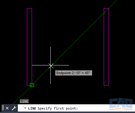
Combine OSNAP with polar angles for fast, precision drafting.
Shortcut 3 — Use Polar Tracking During Modify Commands
You can use polar vectors during:
- MOVE
- COPY
- STRETCH
- ROTATE (basepoint alignment)
- OFFSET (direction selection)
Example: Move a column 10 feet along a 30° grid line:
- Select column
- Move
- Choose basepoint
- Move cursor to 30°
- Type 10’
- Enter
Shortcut 4 — Build Your Own Angle Library
Every long-term CAD user develops their own additional angles based on project types.
For example, if I’m working on structural with roof pitches, I add 18.4°, 26.6°, 30°, 45°, 63.4°, and 71.6° before I even start drawing.

Add custom angles in the Polar Tracking settings window to match real-world engineering slopes, roof pitches, and brace angles.
Troubleshooting – Why Polar Tracking Isn’t Working
Sometimes, Polar Tracking can appear “broken” even when the fix is simple.
1. Wrong Increment Angle
If your increment angle is 90°, you won’t get 30°, 45°, or 60° unless they’re added as Additional Angles.
2. ORTHO is Overriding
If ORTHO is on:
- ORTHO wins
- Polar Tracking only works at the orthogonal angles
3. POLAR is Off
Always check the status bar.
4. OSNAP Tracking Interference
Tracking vectors from OSNAP points can visually compete with polar vectors.
5. Cursor Not Close Enough to the Angle
Move slightly above or below the desired direction.
6. Dynamic Input Conflict
Sometimes DYN settings can mask angle data.
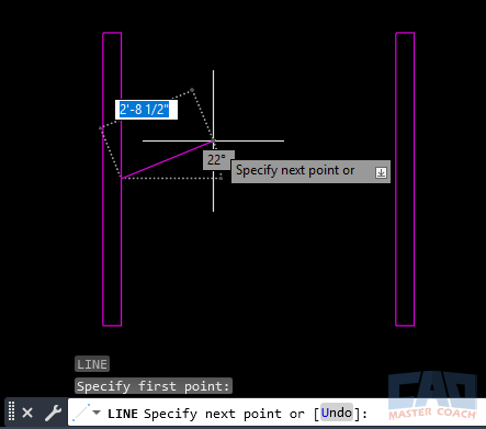
Most Polar Tracking problems come from angle settings that don’t match the intended geometry.
Related Commands and Tools
These drafting aids are often used together:
| Command / Tool | Description |
|---|---|
| ORTHO | Locks cursor movement to horizontal and vertical directions for precise linear drafting. |
| Polar Tracking | Guides cursor movement along preset angles, helping you draw angled lines accurately. |
| Object Snap Tracking | Projects temporary alignment paths from OSNAP points to help you line up new geometry. |
| OSNAP | Locks onto precise geometric points like endpoints, midpoints, and intersections. |
| Dynamic Input | Displays distances, angles, and command prompts at the cursor for more intuitive drafting. |
| Direct Distance Entry | Allows you to enter exact distances simply by moving the cursor in a direction and typing a value. |
FAQs — Polar Tracking (AutoCAD)
No. ORTHO locks your cursor to horizontal and vertical. Polar Tracking allows any angle you choose.
You likely need to add it to Additional Angles or adjust the increment angle.
Yes, they are independent — but they complement each other extremely well.
Open DSETTINGS, go to the Polar Tracking tab, and add your angle to Additional Angles.
ORTHO is probably turned on.
