ORTHO Command in AutoCAD
AutoCAD ORTHO Command Access
COMMAND LINE: ORTHO

DEFAULT KEYBOARD SHORTCUT: OR / F8
STATUS BAR: ORTHO BUTTON

Introduction
ORTHO is one of the oldest and most reliable drafting aids in AutoCAD. When activated, it restricts your cursor movement to perfectly horizontal and vertical directions—nothing in between. For anyone drawing floor plans, elevations, sections, mechanical layouts, or structural framing models, ORTHO quickly becomes a go-to tool for maintaining accuracy.
Although simple, ORTHO solves a very real problem many beginners experience: slight cursor drift. Without ORTHO, it’s easy to accidentally draw at a 1°, 2°, or 3° angle when you intended to draw straight. ORTHO fixes this by giving you confident, predictable movement along the X and Y axes.
In this article, you’ll learn how ORTHO works, how to toggle it quickly, when it should (and shouldn’t) be used, and how it interacts with other drafting aids like Polar Tracking and Object Snap Tracking. You’ll also see examples from real engineering workflows and learn the most common mistakes to avoid.
What ORTHO Does
ORTHO is simple in concept but powerful in impact. When turned on, it constrains cursor movement to 0° or 90°—perfectly horizontal or vertical—relative to your current UCS.
This means:
- You can only draw straight horizontal or vertical lines
- Cursor movement snaps to X and Y directions
- Diagonal movement is completely disabled
- You gain precise control when drafting orthogonal geometry
ORTHO does not change:
- Object Snap behavior
- Polar Tracking settings
- Tracking vectors
- Angle input when typing explicit angles
It only restricts cursor motion.
This makes it ideal for fast, accurate drafting—especially for students and beginners learning to control their cursor.
How to Turn ORTHO On and Off
ORTHO can be activated three different ways. You’ll likely use all of them, depending on your workflow.
Using the Keyboard (F8)
Pressing F8 toggles ORTHO mode on or off instantly.
For most professionals, the F-keys are faster than clicking icons. Toggling ORTHO through F8 becomes muscle memory over time.
Tip for laptop users:
Some laptops require pressing Fn + F8 if function lock is enabled.

The ORTHO icon on the AutoCAD Status Bar turns blue when active and grey when inactive.
Typing the Command
- You can also activate ORTHO using the command line: ORTHO
- AutoCAD will prompt: Enter mode [ON/OFF]:
- Choose the option you want.
- You can also change the system variable: ORTHOMODE
- Set to 1 for ON, 0 for OFF.
Using the Status Bar
On the AutoCAD Status Bar at the bottom of your screen, you’ll see the ORTHO icon.
- Blue = ON
- Grey = OFF
Click it anytime to toggle the mode.
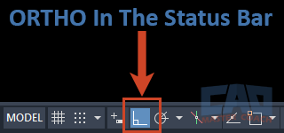
Click the ORTHO icon on the Status Bar to toggle the mode on or off.
When to Use ORTHO
ORTHO shines in situations where accuracy and clean alignment matter most. Any time you’re working within an orthographic layout—whether drafting architectural floor plans, structural grids, equipment layouts, or simple geometric frameworks—ORTHO provides reliable directional control that keeps the drawing crisp and organized. It’s especially helpful when you need to maintain perfect horizontal and vertical alignment between elements or when creating geometry that must follow a strict rectangular form. ORTHO also speeds up repetitive drafting tasks because you no longer have to worry about cursor drift or minor angle errors. When precision and efficiency are the goal, ORTHO becomes an essential part of your everyday drafting workflow.
Creating Orthographic Geometry
Most drafting in engineering is orthographic—meaning everything is arranged along perpendicular axes.
Use ORTHO for:
- Drawing straight lines
- Creating rectangles or room outlines
- Drafting walls, beams, and grids
- Laying out furniture or equipment in a plan
- Aligning geometry along the X/Y directions
For foundational plans or any grid-based layout, ORTHO drastically improves control.
Editing Tasks
ORTHO is equally valuable when editing existing drawings.
Use ORTHO when:
- Moving objects exactly left, right, up, or down
- Copying elements along straight lines
- Stretching elements that should remain horizontal/vertical
- Extending lines or polylines
- Aligning dimensions and labels
If a command involves direction or movement, ORTHO can help you maintain precision.
When the Cursor Feels “Slippery”
Students often struggle with control in early drafting. The cursor wanders just slightly off axis, causing awkward diagonal lines.
Turning on ORTHO eliminates that entirely. It gives beginners confidence while encouraging consistent drafting habits.
When NOT to Use ORTHO
As helpful as ORTHO is, there are times when it becomes more of an obstacle than a tool. ORTHO restricts your cursor movement to only horizontal and vertical directions, which is great for rectangular geometry but extremely limiting when your design requires angled lines, slopes, or non-orthogonal features. In these situations, ORTHO prevents you from freely following the geometry you actually need to draw, often leading users to think something is “wrong” with AutoCAD. When working with angled components, roof pitches, mechanical systems, property bearings, or any geometry that doesn’t fall neatly along the X or Y axis, ORTHO should be turned off so you can draft naturally and accurately. Keeping ORTHO active in these scenarios can cause frustration, misalignment, and extra clicks—so knowing when to disable it is just as important as knowing when to rely on it.
Turn ORTHO off when:
- Drawing angled geometry
- Drafting roof slopes or ramps
- Modeling mechanical components with specified angles
- Using Object Snap Tracking to follow angled vectors
- You need Polar Tracking to guide angles other than 0° or 90°
The most common beginner mistake:
They forget ORTHO is on and can’t understand why they can’t draw diagonal lines.
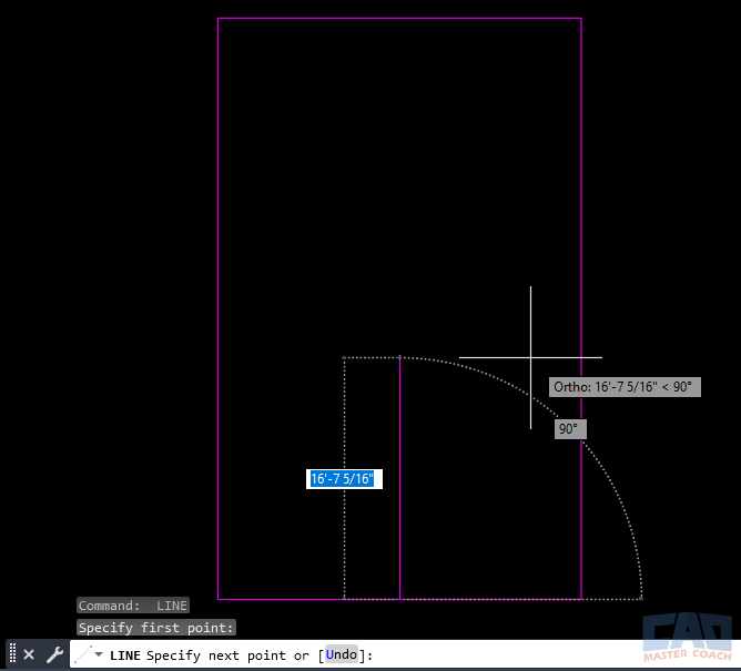
With ORTHO enabled, the cursor snaps only horizontally or vertically.
ORTHO vs Polar Tracking
These two drafting aids often get confused. Both are angle-related, but they serve different purposes.
| Feature | ORTHO | Polar Tracking |
|---|---|---|
| Movement | Locks cursor to 0° and 90° only | Allows custom angles (e.g., 30°, 45°, 90°) |
| Flexibility | Strict — only horizontal/vertical | Flexible — works for any angle |
| Best Use | Orthogonal geometry, grids, floor plans | Angled drafting, architecture, MEP layouts |
| Can They Work Together? | Yes, but ORTHO overrides Polar | Yes, but Polar yields to ORTHO |
Interaction with Object Snap Tracking
Object Snap Tracking (OST) lets you align with temporary reference points—often at custom angles.
ORTHO can interfere with OST in these ways:
- OST vectors at 30°, 45°, or any non-orthogonal direction become inaccessible
- ORTHO will force your cursor to snap horizontally or vertically only
- Tracking lines appear, but you can't follow them unless ORTHO is off
If you want to track at an angle, turn off ORTHO or switch to Polar Tracking.
ORTHO with Common AutoCAD Commands
Line
The Line command is where ORTHO shines the most. When you activate ORTHO and begin drawing a line, your cursor is locked into perfect horizontal or vertical movement. This eliminates the risk of accidentally drafting a line at an unintended angle, such as 1° or 2°, which is a common issue for beginners. Using ORTHO with the Line command ensures that your geometry remains clean, orthogonal, and predictable. This is particularly helpful when creating walls, rooms, structural grids, machinery layouts, or any geometry that relies on a crisp rectangular framework. Professional drafters often toggle ORTHO on and off rapidly while using the Line command, depending on whether they’re drafting straight or angled segments.

With ORTHO enabled, the Line command creates perfectly horizontal and vertical segments for clean, orthographic geometry.
Polyline
When drawing polylines, ORTHO helps create fast, controlled, rectilinear shapes. A polyline allows you to chain together multiple connected segments—horizontal, vertical, or angled—but ORTHO restricts movement so that each click automatically aligns with the X or Y axis. This is ideal for drafting architectural spaces, conduits, duct runs, cabinetry outlines, and structural framing systems. ORTHO prevents wavy or misaligned polyline segments, making your geometric layout cleaner and easier to edit later. It's especially helpful when creating complex orthogonal shapes that must remain perfectly square.
Move
The Move command becomes dramatically more precise when used with ORTHO. With ORTHO turned on, the Move vector locks to either horizontal or vertical directions, meaning objects shift exactly along the X or Y axis. This is extremely useful when adjusting walls, beams, notes, dimensions, blocks, or any geometry that needs to stay aligned in a drawing. Without ORTHO, even a slight cursor drift can cause a move to go off-angle, creating misalignment across your design. When you need to reposition objects cleanly and confidently, toggling ORTHO before initiating the Move command ensures perfect directional control.
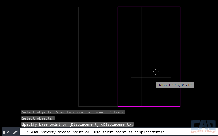
ORTHO locks the Move direction to straight horizontal or vertical paths, ensuring perfect object alignment.
Copy
Using Copy with ORTHO is one of the fastest ways to lay out repeated elements in a clean grid or linear pattern. When ORTHO is active, all copy vectors follow straight horizontal or vertical lines, keeping your duplicated objects perfectly aligned. This is commonly used when copying structural columns down a gridline, repeating desks or furniture along a wall, duplicating equipment in a mechanical room, or copying lights across a reflected ceiling plan. ORTHO helps maintain consistent spacing and prevents accidental diagonal offsets, especially during large repetitive drafting tasks.
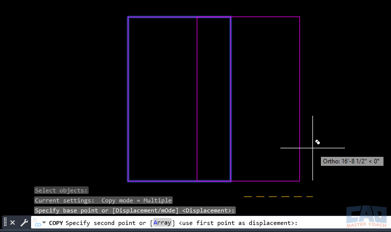
Using ORTHO with the Copy command helps create precise, perfectly aligned copies along a horizontal or vertical path.
Lengthen
The Lengthen command allows you to extend or shorten lines and arcs. When ORTHO is active, you can Lengthen orthogonal elements with perfect control because your cursor movement stays locked to straight horizontal and vertical directions. This prevents distortions caused by dragging at unintended angles and guarantees that extensions maintain alignment with existing geometry. It’s particularly useful when adjusting wall segments, extending structural beams, cleaning up boundary lines, or fine-tuning polyline edges. ORTHO ensures that all adjustments remain square and consistent.
Dimensioning
When placing dimensions in a drawing, ORTHO helps maintain clean, professional alignment—especially for horizontal and vertical dimensions. With ORTHO on, your dimension lines stay perfectly level or perfectly plumb, preventing accidental diagonal placement. This is crucial for readable construction documents, shop drawings, and engineering plans. Clean dimension alignment improves clarity for contractors and eliminates confusion in the field. Whether you're placing linear dimensions, baseline dimensions, or dimension strings, ORTHO keeps your annotation crisp and aligned with the geometry it references.
Real-World Engineering Examples
Civil Engineering
Roadways often follow curves and angles, so ORTHO is usually turned off.
However, ORTHO is perfect when drafting:
- Property boundary rectangles
- Parking lot stalls
- Retaining wall segments
- Channel walls or headwalls
Structural Engineering
ORTHO is essential for:
- Grid layouts
- Beam and column lines
- Shear wall layouts
- Masonry wall plans
- Elevation and section drawing alignment
Mechanical & Electrical
ORTHO helps maintain alignment of:
- Equipment layouts
- Cable trays
- Pipe runs
- HVAC duct runs
- Electrical panels and conduits
Common Mistakes With ORTHO
“AutoCAD won’t draw at an angle!”
ORTHO is on. Press F8.
Polar Tracking doesn’t seem to work
ORTHO always overrides it.
Cursor locked to only four directions
ORTHO is on.
Laptop F-keys not responding
You may need to press Fn + F8.
Snapping seems inconsistent
Some users confuse OSNAP with ORTHO.
OSNAP handles points, ORTHO handles direction.
CAD Master Coach Tips
Tip 1 — Don’t leave ORTHO on all the time
Use it intentionally. Professional drafters toggle ORTHO dozens of times per hour.
Tip 2 — Combine ORTHO with Direct Distance Entry
Click a start point → move in a locked direction → type a value → press Enter.
Fast, accurate, reliable.
Tip 3 — Think ahead in terms of direction
Develop the habit of pointing your cursor first, then typing distances.
Tip 4 — Use Polar Tracking for angles, then return to ORTHO
This back-and-forth switching is how professionals control geometry with precision.
Tip 5 — Train your muscle memory for F8
This speeds up your workflow more than most new users realize.
Practice Exercise
Try this simple exercise to practice ORTHO:
- Draw a rectangle roughly 40' x 20'.
- Offset the long sides inward by 5’.
- Copy four columns into the interior using ORTHO.
- Move one column exactly 10' right using ORTHO.
- Add horizontal and vertical dimensions around the layout.
This helps you internalize ORTHO movement and directional locking.
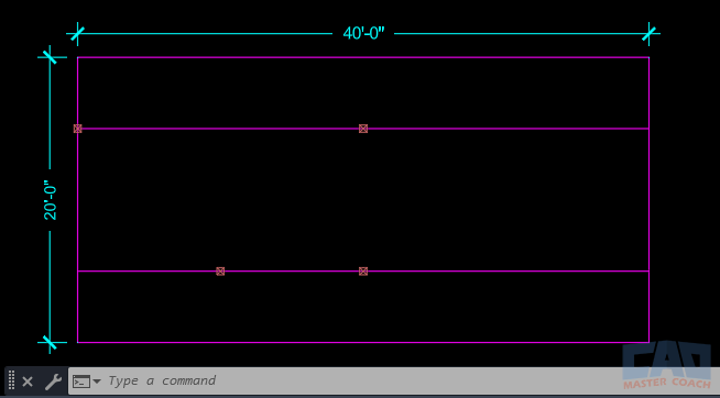
A simple practice layout for learning ORTHO, offsets, copies, and dimensions.
Summary
ORTHO is one of the most useful drafting aids in AutoCAD because it provides instant control over straight-line movement. When accuracy and alignment matter, ORTHO offers predictable, precise cursor behavior. By learning how to toggle ORTHO quickly—and when to use it versus Polar Tracking or Object Snap Tracking—you’ll draft faster and with fewer errors.
Use ORTHO for orthographic geometry, grids, plans, and structural layouts. Turn it off for angled drafting or when Polar Tracking is needed. With practice, ORTHO becomes a natural part of a fast, professional workflow.
Related Commands and Tools
| Command / Tool | Description |
|---|---|
| ORTHO | Locks cursor movement to horizontal and vertical directions for precise linear drafting. |
| Polar Tracking | Guides cursor movement along preset angles, helping you draw angled lines accurately. |
| Object Snap Tracking | Projects temporary alignment paths from OSNAP points to help you line up new geometry. |
| OSNAP | Locks onto precise geometric points like endpoints, midpoints, and intersections. |
| Dynamic Input | Displays distances, angles, and command prompts at the cursor for more intuitive drafting. |
| Direct Distance Entry | Allows you to enter exact distances simply by moving the cursor in a direction and typing a value. |
FAQ
ORTHO is turned on. Press F8 or toggle the icon on the Status Bar.
No. ORTHO only controls cursor direction, not snapping to endpoints, midpoints, or intersections.
Yes, but ORTHO takes priority. If both are active, Polar Tracking angles won’t show.
Press F8 to turn ORTHO on or off instantly.
You have ORTHO enabled. Turn it off to regain free movement.
