The Philosophy of Layer Management in AutoCAD
Introduction: Why Layers Are More Than Just Lines
Every AutoCAD user, whether a beginner drafting their first floor plan, or a seasoned architect managing complex projects, eventually runs into the same question: Why do layers exist?
At first glance, they seem like a technical necessity, a place to group lines, hatches, text, and dimensions. But in truth, layers are more than organizational buckets; they are the digital reflection of how the real world of construction and design is divided. Layers embody the philosophy of separation, hierarchy, and control. When used well, they streamline the design process, reduce errors, and ensure consistency across teams. When mismanaged, they lead to chaos: drawings that are impossible to navigate, information that disappears when plotted, and confusion across disciplines.
This article takes a deep dive into the philosophy behind layer management in CAD. We’ll explore why layers exist, how they mimic construction trades, how concepts like visibility and plotting hierarchy shape workflow, and what happens when “layer sprawl” takes over.
1. Why Layers Exist in the First Place
Before AutoCAD, drawings were produced on paper, vellum, or Mylar using ink and pencil. Drafting teams relied on physical overlays—transparent sheets stacked one on top of another. One overlay might contain walls, another electrical layouts, another plumbing, and so on. By stacking and unstacking overlays, drafters could see specific scopes of work independently or in combination.

In the image above, all lines are in the same location in Model Space. Through layer states and manipulating the visibility of the desired layers to be seen, three distinct views of the building can be shown: Demo Plan, Floor Plan, and Shearwall Plan.
AutoCAD layers are the digital evolution of that system. They exist to replicate three critical needs from the hand-drafting era:
1.1 Organization of Information
- By categorizing elements (walls, doors, hatches, dimensions, notes), layers make it possible to structure complex drawings logically.
- Instead of a chaotic pile of geometry, layers give every object a home.
1.2 Control of Visibility
- Just like physical overlays could be lifted or removed, AutoCAD layers can be turned on or off. This allows drafters to isolate certain aspects of a project without distraction.
1.3 Efficiency in Revisions
- Construction projects evolve constantly. By grouping objects into layers, designers can update a system (say, electrical) without accidentally interfering with architectural or structural elements.
In other words, layers exist not just for technical convenience, but to preserve clarity and intent across the entire life of a drawing.
2. Layers as a Mirror of Construction Trades
The brilliance of the layer concept is how closely it mimics the real world of construction. Buildings are not created by one monolithic trade; they are assembled through the coordination of many specialized disciplines:
- Architectural: walls, doors, windows, finishes
- Structural: beams, columns, foundations
- Mechanical: ducts, HVAC equipment
- Electrical: wiring, outlets, lighting
- Plumbing: piping, fixtures
Each trade requires its own information set, yet all of them must fit together in a coordinated model. Layers, therefore, serve as the digital handshake between trades.
When an architect sends a DWG file to an electrical engineer, the electrical designer doesn’t need to see every furniture hatch or ceiling grid. By turning off irrelevant layers, they can focus on their scope without distraction. Conversely, when the drawing comes back, the architect can check that new wiring does not conflict with their design intent.
Thus, layers reinforce the principle of specialization with coordination—a cornerstone of construction philosophy.
3. Visibility Control: Seeing What Matters
At the heart of layer management is visibility control. This is the ability to decide what is shown and what is hidden in a given drawing or viewport.
- On/Off vs. Freeze/Thaw
- On/Off: Hides layers from view, but objects still regenerate in the background.
- Freeze/Thaw: Removes layers from memory entirely, improving performance on large projects.
- Viewport Overrides
- AutoCAD allows a layer to be visible in one viewport and invisible in another. For example, dimensions may appear on a plan sheet but be hidden in a 3D axonometric.
- Transparency & Color Control
- Beyond simple visibility, layers also allow adjustments to lineweight, color, and transparency. A background reference can be greyed out to reduce visual noise while keeping it legible.
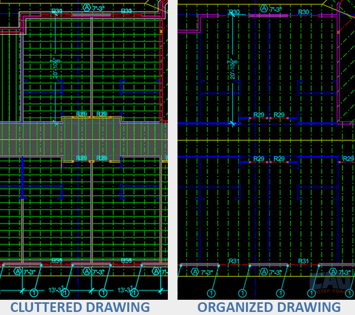
The image above shows the same location in the drawing in two different layer visibility states. On the left, all layers are Thawed and On and the drawing is a mess. On the right only the layers that are relevant to see while working at this part of the building are Thawed and On while the rest of the layers are Frozen.
Go here for a deep dive into the LAYER command.
Visibility control is not just technical, it’s philosophical. At its core, visibility control about clarity of communication. A construction drawing is not merely a picture; it’s a contract. Every line carries meaning, and layers ensure that meaning is conveyed to the right person at the right time.
4. Plotting Hierarchy: What Prints, What Doesn’t
Plotting hierarchy is where layer philosophy meets the real-world consequences of mismanagement. When a drawing is plotted, the arrangement of lineweights, colors, and visibility determines whether the result is clear or confusing.
- Lineweights as Hierarchy
- Thicker lines for walls, thinner lines for fixtures, dashed lines for overhead items. This visual hierarchy reflects real-world importance.
- Non-Plot Layers
- Construction drawings often require guidelines, notes to self, or references that should never appear on a finished sheet. Non-plot layers preserve working information without cluttering the deliverable.
- Plot Style Tables (CTB/STB)
- Layer colors are often tied to pen assignments, determining lineweight and plotting behavior. This is where consistency becomes critical—one misassigned color can wreck the entire plotting hierarchy.
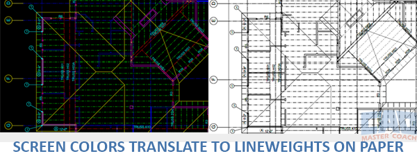
The image above shows how the same lines look on the screen in Model Space, and then when plotted in Paper Space. The colors and layers have all been assigned lineweights, so they plot in a readable way. In short, Line Colors in Model Space = Lineweights in Paper Space.
Plotting, in essence, is where philosophy becomes practice. A perfectly layered drawing that prints poorly has failed its ultimate test.
Get the Top 35 AutoCAD Commands for FREE
5. Discipline Standards: Speaking a Common Language
No matter how logical your personal layer setup may seem, it only has value if it can be understood by others. That’s where discipline standards come in.

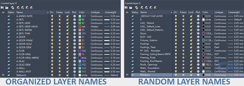
In the image above, the layer system on the left is haphazard and a mess. Layer names seem to be made up and as a result, they are likely different from project to project. In addition, nearly all of the layers have been assigned the color white, a linetype of continuous, and the lineweights are nearly all the same.
By contrast, the layer system on the right follows AIA guidelines using different colors for each layer, different linetypes, and each layer has been assigned it’s own lineweight to make the plotted drawing look visually appealing.
National CAD Standards (NCS) Example
Many firms adopt or adapt the U.S. National CAD Standard, which suggests naming conventions like:
- A-WALL-NEW (Architectural, wall, new)
- S-COLN-EXST (Structural, column, existing)
- E-LITE-EMER (Electrical, lighting, emergency)
This structure ensures that:
- Anyone opening the file can immediately understand the scope.
- Different trades don’t overwrite or duplicate each other’s layers.
- Automated tools (scripts, layer filters, BIM imports) can parse drawings reliably.
Custom Standards
Smaller firms often build their own systems—simpler, but equally valid if applied consistently. The key is discipline. A single rogue layer like “Layer1” or “Misc” undermines the philosophy of order.
6. The Problem of Layer Sprawl
If layers exist to create clarity, then their misuse creates the opposite. Layer sprawl occurs when a drawing accumulates too many layers, often with redundant or ambiguous names. Symptoms include:
- Layers like “WALL,” “Walls,” “MyWalls,” all describing the same thing.
- Hundreds of layers imported from external references that are never cleaned up.
- Users creating ad-hoc layers without following standards.
Layer sprawl has philosophical consequences: it dilutes meaning. A system built to ensure clarity instead becomes a swamp of inconsistency.
In the image above, the layer system on the left uses AIA layer standard names and conventions, while the layer system on the right uses an unorganized and random layer system that is difficult to follow and make sense of.
Causes of Layer Sprawl
- Copy-Paste Across Projects: Imported blocks bring their own layer definitions.
- Lack of Training: Users don’t understand standards or why they matter.
- Software Defaults: Tools like Revit exports can create dozens of unnecessary layers.
How to Avoid It
- Layer Filters & Groups: Use filters to organize, rather than create new layers.
- Regular Audits: Periodically purge unused or duplicate layers.
- Templates: Start every project from a clean template with pre-defined, approved layers.
- Training & Culture: Reinforce the philosophy behind layers—not just the mechanics.
7. Philosophical Lessons from Layer Management
Layer management is not simply a technical workflow—it reflects larger truths about design, construction, and collaboration.
- Clarity is Communication
- Layers are about telling the right story to the right audience. Without clarity, drawings fail in their purpose.
- Structure Enables Freedom
- Far from being restrictive, a disciplined layer system frees designers to work creatively, knowing the underlying order will keep the drawing coherent.
- Simplicity Over Complexity
- The temptation to create more layers often undermines efficiency. Simplicity—fewer, well-defined layers—usually produces stronger results.
- Philosophy Scales With Technology
- Whether drafting in AutoCAD, modeling in Revit, or exporting to BIM coordination tools, the same philosophy applies: separate, organize, control, communicate.
8. Practical Strategies for Better Layer Management
To tie philosophy back into practice, here are actionable strategies:
- Adopt a Standard and Stick to It
- Whether NCS or in-house, consistency matters more than perfection.
- Use Clear, Descriptive Names
- Avoid “Layer1” at all costs. Use names that communicate scope, discipline, and intent.
- Leverage Non-Plot Layers
- Keep your working notes and references in the file, but never let them contaminate final deliverables.
- Train New Team Members
- Don’t assume everyone knows the system. A 30-minute orientation on layer standards saves hours of cleanup later.
- Regularly Purge & Audit
- Treat layer cleanup as part of the design process, not an afterthought.
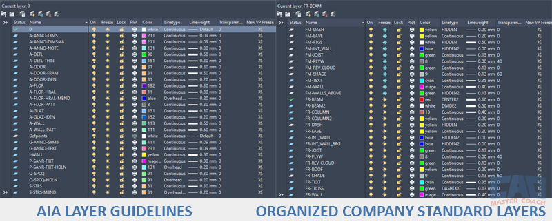
No matter what layer system you choose, make it organized and clear. Whether you use a national layer standard, or a layer system developed within your company, rigorously adhering to the rules of the layer system you use will make your drawings easier to use, easier for others to edit, and make your work faster and more efficient.
9. Conclusion: Layers as a Philosophy of Order
In the end, layers are about more than just lines on a screen. Layers are the core of a philosophy: that complex systems can only function when divided into understandable parts. Just as construction relies on trades working in harmony, AutoCAD relies on layers to maintain clarity, consistency, and control.
When used wisely, layers make design powerful. When abused, they turn clarity into confusion. The choice rests with the user—but the philosophy remains the same: organize, communicate, and respect the system.


