Mastering Layers in AutoCAD
Mastering Layers in AutoCAD: The Complete Beginner’s Guide to Layer Management & Standards
Table of Contents
Introduction
Real Life Story - The Layer Problem That Costs Hours
1. The Purpose of Layers in AutCAD
2. Setting Up Your Layer System
3. Managing Layers Efficiently
4. Layer Standards and Templates
5. The 10 Most Common AutoCAD Layer Mistakes (and How to Avoid Them)
6. Industry Standards and Best Practices
7. Wrapping It All Up
Introduction
If you’re just starting out with AutoCAD, layers might feel like an optional feature — something you’ll “figure out later.” But here’s the truth: layers are not optional. They’re the backbone of every drawing, the difference between clean, professional files and chaotic, unmanageable ones.
Think of layers like transparent sheets on a drafting table. One sheet for walls, one for furniture, one for dimensions, another for electrical. Together they create a complete picture, but each can be controlled independently — turned on or off, printed with different lineweights, or locked to prevent mistakes.
Whether you’re designing a simple floor plan or collaborating on a multi-discipline project, understanding how to use AutoCAD layers properly is essential. And the earlier you learn to manage them well, the fewer headaches you’ll face down the road.
In this guide, we’ll walk through everything you need to know about layers in AutoCAD — from the basics of naming and color assignments to professional standards, common mistakes, and even when it’s okay to bend the rules.
Real Life Story – The Layer Problem That Costs Hours
Imagine this: You open a DWG from a subcontractor and see every single object—walls, text, electrical symbols, dimensions—dumped into Layer 0. Linetypes are inconsistent, colors mean nothing, and the plot preview looks like a random collage. You spend the next two hours isolating entities, reassigning them, and trying to guess what’s supposed to be what. This is not just frustrating, it’s an expensive drain on project time.
For seasoned drafters and CAD managers, poor layer management is one of the fastest ways to derail a project. For newer users, it can cause confusion and errors that ripple into construction. The good news: AutoCAD’s layer system is robust, and when used correctly, it can make your drawings cleaner, faster to edit, easier to read, and compliant with industry standards.
This guide is your technical deep dive into mastering layers—not just the basics, but also advanced tools, standards, and workflows that keep your drawings sharp and your productivity high.
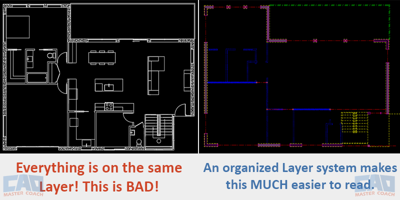
Image: Client sends a drawing with everything on the same layer, making the need to convert all lines to an organized layer system.
1. The Purpose of Layers in AutoCAD
Layers in AutoCAD are essential for organizing the components of a drawing. Think of them like transparent sheets stacked over a light table — each one holds a different category of information. Instead of mixing everything on one layer, you separate walls, furniture, electrical lines, text, dimensions, and more. This makes your drawing easier to read, manage, and modify.
Each layer controls key visual properties: color, linetype, lineweight, and plot behavior. You can also hide, lock, or freeze layers to reduce visual clutter or protect information while editing other parts of your design.
Why Use Layers?
- Visual Clarity: Layers help you immediately distinguish between architectural, structural, electrical, and annotation elements. Color-coding and line styles make your drawings easier to navigate and understand at a glance.
- Efficient Editing: Lock or freeze specific layers so you can work on one part of the drawing without disturbing others. This is especially helpful in complex projects with many overlapping elements.
- Professional Output: Layers allow you to assign specific plot styles—such as different lineweights or colors—so your printed drawings look polished and follow industry standards.
- Team Collaboration: Standardized layer structures mean that anyone opening your drawing can quickly make sense of it. This is critical in offices or across teams where multiple people interact with the same file.
In short, layers are not just the best practice, they’re a fundamental part of working smart in AutoCAD.
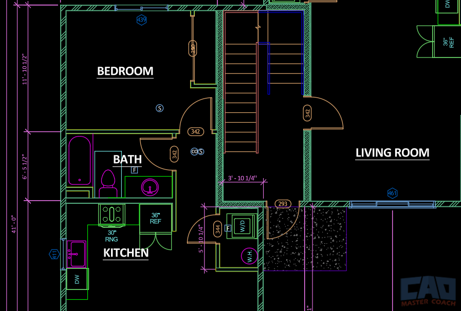
In the image above, similar objects are on the same layer, and each layer is a different color, making the drawing easier to read on the screen. The layers and colors are defined to plot as different line weights, making the drawing easy to read on paper, or in a pdf file.
2. Setting Up Your Layer System
Once you understand what layers do, the next step is setting up a clear, consistent layer system. This ensures your drawing stays organized from start to finish and remains understandable to others—whether they’re coworkers or future you.
2.1 Naming Conventions
Layer names should be meaningful, consistent, and easy to scan. A common format for residential architecture is:
Discipline–Category–Status
This format keeps everything structured and searchable.
Examples:
- A-WALL-EXST – Architectural, walls, existing
- A-WALL-NEW – Architectural, walls, new
- A-DOOR – Architectural, doors
- A-FURN – Architectural, furniture
- E-RECP – Electrical, receptacles
- E-LTNG – Electrical, lighting
- S-BEAMS – Structural, beams
- S-COLS – Structural, columns
- T-ANNO-DIMS – Text, annotations, dimensions
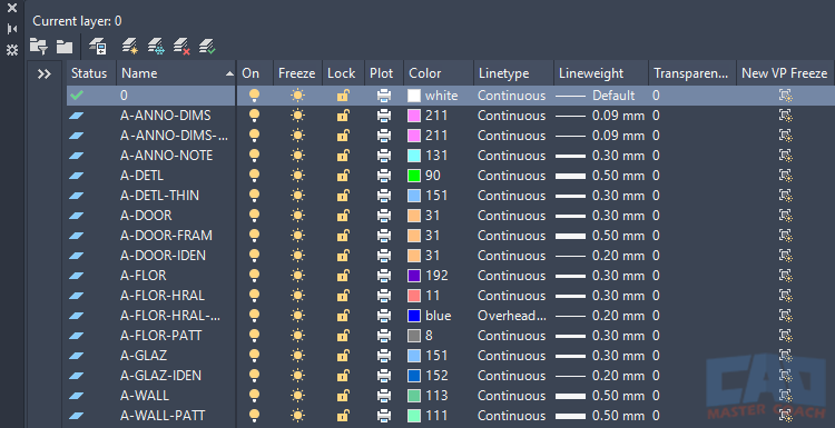
The image above shows an example of an AutoCAD Layer System. Note the layer names, color, and lineweight. The lineweight column indicates lineweight when the drawing is plotted.
2.2 Color Assignments
Colors in AutoCAD aren’t just visual — they often drive how things plot when using a CTB (color-dependent plot style). A well-thought-out color scheme makes your on-screen drawing easy to read and ensures your printed output is clean and professional.
Example color scheme (CAD Master Coach visual identity):
- Walls – Color 6 (Magenta)
- Doors – Color 2 (Yellow)
- Windows – Color 5 (Blue)
- Furniture – Color 3 (Green)
- Electrical – Color 1 (Red)
- Dimensions – Cyan 4 (Cyan)
2.3 Linetypes and Lineweights
Linetypes and lineweights add another layer (pun intended) of meaning to your drawings.
Common linetypes:
- Continuous – For visible, structural elements
- Hidden – For elements above, below, or behind the cut plane
- Center – For symmetry, axes, or centerlines
- Dashdot – For special or symbolic elements (like fire barriers or zone lines)
Standard lineweight hierarchy:
- Walls: 0.40 mm – Strong visual priority
- Doors/Windows: 0.25 mm – Secondary structural items
- Furniture: 0.20 mm – Light but visible
- Annotations/Text/Dimensions: 0.35 mm – Legible, not as prominent as walls
Keeping linetypes and lineweights consistent ensures your printed plans are easy to interpret, especially when viewed at a distance or in low resolution.
3. Managing Layers Efficiently
Knowing how to create layers is one thing. Managing them well—especially in complex drawings—is where real productivity happens. AutoCAD gives you several tools to keep your layer system fast, flexible, and under control. Whether you're working solo or collaborating with others, mastering these tools is non-negotiable.
3.1 Layer Properties Manager: Your Command Center
The Layer Properties Manager is where you create, delete, modify, and organize layers. Open it with LA on the command line or by clicking the Layer Properties button on the Home tab.
Here is some of what you can do in the Layer Properties Manager:
- Change layer names, colors, linetypes, lineweights
- Freeze, lock, or turn layers on/off
- Set a layer as current
- Filter layers (by name, status, or properties)
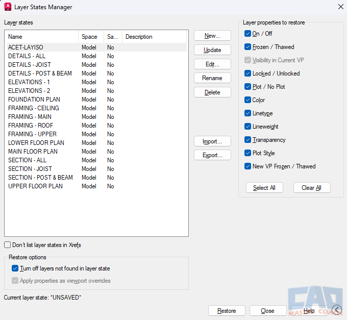
3.2 Layer States: Save Your Sanity
Have you ever spent 10 minutes setting up they layer system for a drawing, which layers are visible, frozen, or locked—only to lose it all because someone else changed the file?
That’s what Layer States are for. Think of them as snapshots of your layer settings. You can save a configuration, then restore it anytime.
Use Layer States to:
- Switch between presentation views (e.g., Electrical vs. Plumbing)
- Share layer setups between files
- Protect your plotting layout from accidental changes
Access Layer States from the Layer Properties Manager or with the LAYERSTATE command.
3.3 Layer Tools You Should Actually Use
AutoCAD’s Home tab has a group of layer tools most beginners overlook—but they’re huge time-savers.
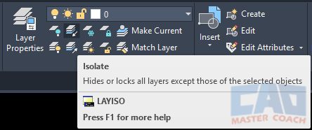
- LAYISO (Layer Isolate): Temporarily hides all layers except the one(s) you select. Great for focusing in busy drawings.
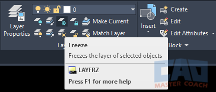
- LAYFRZ (Layer Freeze): Click on an object, and AutoCAD freezes its layer.
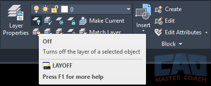
- LAYOFF: Same as above, but it turns the layer off instead of freezing it.
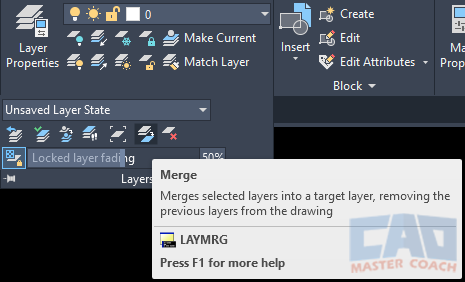
- LAYMRG (Layer Merge): Combine two layers by moving all objects from one into another—then delete the original.
- LAYWALK: A hidden gem. Walk through each layer one by one to see what’s on it. Super useful for cleaning up unfamiliar files.
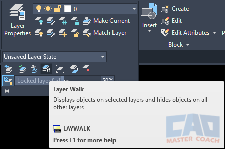
3.4 Purge and Clean Up
Messy drawings slow you down. Use the PURGE command to remove unused layers (along with other clutter like blocks and linetypes). Just be careful—once a layer is purged, it’s gone.
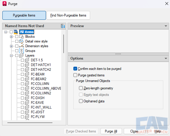
The image above shows all unused layers in the drawing that are eligible to be purged.
3.5 Teamwork = Layer Discipline
In a team environment, layer chaos becomes a productivity killer. Establish a shared template with predefined layers, colors, and lineweights. Store it in a common folder, and make sure everyone uses it.
Get the Top 35 AutoCAD Commands for FREE
4. Layer Standards and Templates
Once you’ve got the hang of layers, the next step is building a system you can reuse and scale. Whether you’re working on your own or with a team, standardized layers and custom templates will save you hours of repetitive setup — and ensure every drawing meets a consistent, professional standard.
This section walks through how to build and apply your own layer standards, create templates, and enforce them using built-in AutoCAD tools.
4.1 Why Standardization Matters
Here’s the reality: consistency is productivity. If every drawing starts from scratch with different layer names, colors, or lineweights, you're wasting time. Worse, you’re introducing room for errors — like printing with incorrect lineweights or missing key layers.
Benefits of a standardized layer system:
- Faster project setup
- Clear expectations for team members or consultants
- Fewer plotting mistakes
- Easier QA and corrections
- Better handoff to clients or permit reviewers
You don’t need a giant enterprise to justify standards — even solo designers can benefit from a streamlined, repeatable workflow.
4.2 Build a Layer Naming Standard That Works
You don’t have to invent one from scratch — there are industry standards out there like the National CAD Standard (NCS), which uses a structure like:
Discipline–Major Group–Minor Group–Status
For example:
- A-WALL-FULL-NEW = Architectural / Wall / Full Height / New
- E-POWR-RECP-EXST = Electrical / Power / Receptacles / Existing
But if that feels like overkill for your workflow, keep it simpler with a 3-part format like:
Discipline–Category–Status
That gives you clean, scalable names like:
- A-WALL-NEW
- A-DOOR
- E-LTNG
- S-BEAMS
- S-COLS
- T-ANNO-DIMS
4.3 Creating a Drawing Template (.DWT)
The best way to reuse your layer setup is by building a drawing template file (.DWT). A DWT file is just a DWG with some extra intent — it’s the foundation for every new project.
4.4 Layer States
A Layer State is a saved configuration of layer settings. Use them to:
- Quickly switch between construction view and presentation view.
- Prepare print-ready states without manually toggling dozens of settings.
4.5 Layer Overrides
In viewport-specific overrides, you can change layer color, linetype, or lineweight only in one viewport without affecting the global drawing.
This is critical for multi-scale layouts where details require different visual emphasis.
4.6 Versioning and Evolving Your Layer System
Your first standard won’t be perfect — and that’s fine. Over time, update your layer system based on real-world feedback:
- Are certain layer names confusing?
- Are colors too similar on screen or too hard to read when plotted?
- Are you missing categories you end up adding manually in every project?
Schedule time every few months to revise your template and DWS file. Keep a version history and communicate changes to your team.
4.7 CAD Master Coach Download: Grab Our Free Starter Template
Ready to jumpstart your layer setup?
Download the free CMMC-Starter-Layers.dwt template with prebuilt layers, colors, linetypes, and lineweights — all following the standards covered in this article
This is the same structure used in real-world residential and light commercial projects. Save time, reduce mistakes, and start drawing like a pro.
5. The 10 Most Common AutoCAD Layer Mistakes (and How to Avoid Them)
If there’s one universal truth in AutoCAD, it’s this: bad layer habits will catch up with you. Maybe not in the first week, but eventually your drawing will grind to a halt under its own chaos. You’ll spend more time searching, fixing, and replotting than actually designing.
The good news? Most mistakes are predictable — and preventable. Let’s break down the most common layer pitfalls, why they happen, and how to avoid them.
5.1 Putting Everything on Layer 0
The Mistake: Beginners (and yes, even veterans on bad days) dump every object on Layer 0 because it’s quick and easy.
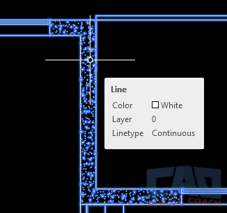
In the image above, everything is on Layer 0, including the exploded HATCH, which makes this drawing very difficult to work with. In addition, all drawing objects are assigned a color and a linetype. It is best to assign the color and linetype to everything on a layer to be “By Layer”.
Why It’s a Problem:
- Layer 0 was never meant to hold your entire drawing. It exists primarily as a neutral placeholder inside blocks.
- When everything lives on Layer 0, you lose all visibility control. Freezing, isolating, or plotting selectively becomes impossible.
- It also screams “rookie move” to anyone opening your file.
The Fix:
- Use Layer 0 only inside block definitions. Leave objects on Layer 0 inside the block, then assign the block itself to the correct layer. This allows the block to inherit layer properties.
- For everything else, always assign objects to meaningful layers.
5.2 Using Random Colors
The Mistake: Picking colors on the fly and setting each object’s color because they “look nice” on screen.
Why It’s a Problem:
- In AutoCAD, colors are not just visual — they usually control plot styles (lineweight, screening, or whether something even prints at all).
- Random colors = unpredictable, messy plotting.
- On large projects, it also confuses team members. Why is this wall magenta? Is it electrical? Furniture? Nobody knows.
The Fix:
- Always follow your layer color standard. Each color should have meaning — walls one color, dimensions another, annotations another.
- If you must add new layers, assign them carefully within your color scheme.
- The color of all objects should be set to By Layer
5.3 Ignoring Lineweights and Linetypes
The Mistake: Leaving everything at “default” lineweight or using only continuous lines.
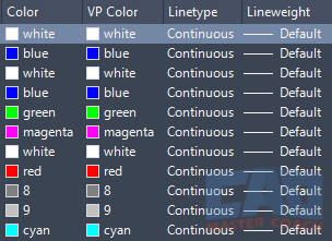
In the image above, all of the lineweights are set to Default.
Why It’s a Problem:
- Your drawings print flat and unreadable. Walls, furniture, and dimensions all look the same and will be very difficult to read. Contrasting lineweights while emphasizing important parts of a drawing make it easier to read.
- Construction documents rely on hierarchy. Lineweight tells the viewer what’s important and what’s background.
The Fix:
- Assign meaningful lineweights to layers (walls thick, furniture thin, text light).
- Use linetypes to communicate meaning: hidden lines for above/below, centerlines for symmetry, dash-dot for special conditions.
CAD Master Coach Tip: Print test plots early. Don’t wait until your deadline to discover your walls are printing the same thickness as your dimensions.
5.4 Not Freezing, Locking, or Isolating Layers
The Mistake: Working in a crowded drawing without using visibility controls.
Why It’s a Problem:
- You slow yourself down by sifting through visual clutter.
- Accidental edits happen — you erase or move objects you didn’t mean to touch.
The Fix:
- Use Freeze to hide layers you don’t need right now.
- Use Lock to make layers visible but untouchable.
- Use LAYISO to isolate just what you want to work on.
5.5 Creating Redundant or Duplicate Layers
The Mistake: Adding “WALLS,” “WALL,” “A-WALL,” and “MY-WALL” all in the same file.
Why It’s a Problem:
- It confuses both you and your team. Which one is correct? Which one plots right?
- It bloats your file with clutter.
The Fix:
- Before creating a new layer, check if one already exists.
- Use LAYMRG (Layer Merge) to consolidate duplicates into a single, clean layer.
5.6 Not Purging Unused Layers
The Mistake: Leaving layers from old Xrefs, blocks, or test geometry clogging your file.
Why It’s a Problem:
- Your layer list becomes overwhelming.
- New users waste time trying to understand what half those layers mean.
The Fix:
- Run the PURGE command regularly.
- Use LAYDEL for stubborn layers you don’t need (but be careful — it deletes objects too).
5.7 Overloading a Single Layer
The Mistake: Stuffing too much into one layer — like putting walls, doors, and windows all on A-WALL.
Why It’s a Problem:
- You can’t isolate or plot those categories separately.
- Editing becomes tedious — you end up selecting and deselecting endlessly.
The Fix:
- Break down layers by logical categories: A-WALL, A-DOOR, A-WIND.
- Use subcategories or status (NEW, DEMO, EXST) when needed.
5.8 Forgetting About Non-Plot Layers
The Mistake: Putting guides, construction lines, or notes on regular layers that actually plot. The DEFPOINTS layer is a layer created by AutoCAD that will not plot. This layer is a great place to put parts of your drawing you don’t intend to print.
Why It’s a Problem:
- You end up with messy, unprofessional prints.
- Critical construction geometry (like centerlines or working grids) can distract from the final presentation.
The Fix:
- Create a dedicated non-plot layer (e.g., X-CONST) and set it to No Plot in the Layer Properties Manager.
- Move all guides and helpers there.
5.9 Ignoring Layer States
The Mistake: Manually toggling layer visibility every time you switch tasks.
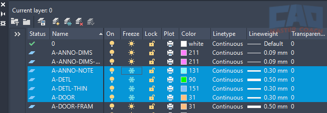
In the image above, the Layer Manager is opened to toggle the state of a few layers. Saving Layer States can automate this for you.
Why It’s a Problem:
- Ignoring Layer States wastes time. As your drawing gets more complicated, managing Layer States will speed up your drafting by at least a factor of 5.
- Increases the chance of forgetting to turn something back on before plotting.
The Fix:
- Save Layer States for different workflows (e.g., “Electrical Plan,” “Furniture Plan,” “Site Plan”).
- Restore them with one click instead of fiddling with checkboxes.
5.10 Skipping Standards Altogether
The Mistake: Treating every drawing as a one-off with its own improvised layer system.
Why It’s a Problem:
- Inconsistent results.
- Painful collaboration — every teammate has to relearn your “system” for every file.
- Extra effort when submitting to clients, cities, or contractors who expect industry standards.
The Fix:
- Use a template (DWT) with your standard layers.
- Enforce CAD Standards company wide, even if you are the only employee.
- Document your rules so your future self (and your team), and do not forget to use them.
Wrapping It Up
Layer mistakes are the #1 cause of AutoCAD chaos. The drawings still “work,” but they’re harder to read, harder to edit, harder to trust, and are very difficult to work with. If you are constantly trying to figure out the layering system of a drawing, you will lose productivity.
Avoiding these pitfalls doesn’t take extra talent — it takes discipline, standards, and the right tools. Think of it like housekeeping: a little daily attention prevents massive cleanups later.
Master your layers, and you master AutoCAD.
6. Industry Standards and Best Practices
Learning to manage layers in your own projects is great. But if you want to work in professional settings — with architects, engineers, contractors, or government agencies — you need to follow industry standards. Standards ensure that everyone is speaking the same “CAD language,” no matter where they are or who trained them.
6.1 What Are CAD Standards?
CAD standards are predefined rules for how drawings should be structured:
- How layers are named
- Which colors and lineweights to use
- Which linetypes represent what
- Annotation styles (text, dimensions, leaders)
- Plotting requirements
Without standards, every drawing is a guessing game. With standards, collaboration becomes smooth — one person’s wall layer is always the same as another’s, across projects, firms, and even industries.
6.2 The National CAD Standard (NCS)
In the United States, the National CAD Standard (NCS) is the most widely recognized system. Developed by the National Institute of Building Sciences (NIBS), it provides a layer naming convention that looks like this:
Discipline Designator – Major Group – Minor Group – Status
Example:
- A-WALL-FULL-NEW → Architectural / Wall / Full Height / New
- S-COLS-EXST → Structural / Columns / Existing
Breakdown:
- Discipline Designator: One or two letters (A = Architectural, S = Structural, E = Electrical, M = Mechanical, etc.).
- Major Group: Broad category (WALL, DOOR, COLS, DUCT).
- Minor Group: Adds detail (FULL, GLASS, DEMO).
- Status: Tells you whether it’s new, existing, to be demolished, or future.
This might feel like alphabet soup at first, but it creates a scalable, universal system. If you work with government clients, larger firms, or multidisciplinary teams, you’ll see NCS (or a variant) again and again.
6.3 International Standards
If you work globally, you may also encounter:
- ISO 13567: An international standard for layer naming and organization.
- Here is a detailed description of the ISO drafting standards on Wikipedia. https://en.wikipedia.org/wiki/ISO_13567
- BS 1192 (UK): Focuses on collaborative production of architectural and engineering drawings.
- DIN Standards (Germany): Often used in European projects.
While the details vary, the idea is the same: consistent naming and categorization so drawings don’t become chaos.
6.4 Office and Firm Standards
Even if you’re not bound by national or international rules, most firms develop in-house CAD standards. These are tailored versions of bigger systems, customized to their workflow. For example:
- A small residential design office may use simplified three-part names (A-WALL-NEW, A-DOOR, E-LTNG).
- A large engineering firm may enforce full NCS compliance with hundreds of layers preloaded in a template.
6.5 Best Practices for Layer Management
Even if you’re not locked into a formal standard, there are universal best practices:
- Use ALL CAPS for layer names. Improves readability and consistency.
- Keep names short but meaningful. Avoid vague names like STUFF or MISC.
- Reserve Layer 0 for block geometry. Nothing else.
- Assign colors by layer, not by object. Keeps everything consistent and easy to manage.
- Use non-plot layers for guides. Always set them to No Plot so they never sneak into your final prints.
- Save Layer States. Don’t manually rebuild visibility settings.
- Clean as you go. Purge unused layers regularly, and merge duplicates.
- Document your system. A simple PDF cheat sheet of layer names, colors, and weights helps everyone stay aligned.
6.6 Adapting Standards to Your Workflow
Here’s the key: standards are guides, not shackles. If you’re working alone on small projects, you may not need the full complexity of NCS. But borrowing from it — like using discipline codes (A, E, M, S) — will future-proof your drawings if you ever collaborate with others, or even when you go back to a drawing months or years later.
Think of standards like grammar rules. You don’t always need academic precision in casual writing, but when you publish or collaborate, following the rules makes your work clear, professional, and respected.
6.7 Building Your Own “Mini-Standard”
If you don’t have to follow NCS, create a personal or office standard. Start small:
- Define your naming convention. Discipline–Category–Status works for most.
- Create a color scheme. Make sure colors map to logical lineweights.
- Assign linetypes. Continuous, hidden, center, dash-dot.
- Document it. A one-page PDF is enough.
- Enforce it with templates and CAD Standards files.
Over time, refine it. Add layers only when necessary. Keep it lean and practical.
6.8 When to Break the Rules
Here’s the truth: standards aren’t religion — they’re tools. And like any tool, sometimes you need to bend the rules to get the job done.
When it’s okay to break them:
- Early design or concept work: In schematic phases, speed often matters more than strict organization. You can refine layers later once the concept is approved.
- Presentation drawings: Sometimes you’ll override standard colors or lineweights to make a client-facing sheet pop visually.
- Small solo projects: If you’re the only one touching the file and the scope is limited, a stripped-down system may be faster.
- Imported or consultant files: Occasionally, it’s easier to adapt a consultant’s layers than force them into your standard.
Beware:
Breaking the rules for convenience is fine if you clean up before final delivery. A concept sketch may get away with “WALLS” on one layer but permit drawings absolutely cannot.
7. Wrapping It All Up
Layers are the backbone of every AutoCAD drawing. Mastering them means more than just keeping your file tidy — it’s about working faster, collaborating smoother, and producing drawings that look professional and print correctly the first time. Industry standards exist for a reason: they make drawings reliable, readable, and universally understood. Whether you follow NCS, ISO, or your firm’s custom rules, what matters most is consistency.
At the end of the day, layers are about communication. You’re not just drafting lines — you’re creating instructions for builders, engineers, inspectors, and clients. Clear standards turn your drawing from a personal sketch into a professional document.
Here’s what we covered:
- What layers do and why they matter — clarity, control, plotting, and teamwork.
- How to set up your system — naming conventions, colors, linetypes, and lineweights.
- Managing layers efficiently — using the right tools, isolating, freezing, and cleaning.
- Templates and standards — building reusable systems and enforcing consistency.
- Common mistakes — and how to avoid falling into the traps that plague beginners.
- Industry best practices — how to align with NCS, ISO, or office standards.
- When to break the rules — staying flexible when creativity or speed demand it.
If you’ve made it this far, you now know more about layers than most everyday AutoCAD users. The difference is you won’t just be drawing — you’ll be drawing with intent, clarity, and professionalism.
What’s Next?
- Put it into practice. Open AutoCAD, create a new drawing, and start building your own layer system using the conventions you’ve learned here.
- Download our free starter template. We’ve done the heavy lifting by setting up a clean, professional layer system you can drop into any project. It’s the fastest way to upgrade your workflow.
👉 Download the CAD Master Coach AutoCAD Layer Template (link placeholder)
- Stay sharp. Layers are just the beginning. Text styles, dimension standards, plotting setups — every part of AutoCAD has best practices that can save you time and make your drawings shine.
As you can see, layer management is not a “nice to have”—it’s the backbone of efficient AutoCAD drafting. A disciplined, consistent layer strategy saves time, improves readability, and reduces costly errors. With the CAD Master Coach AutoCAD Layer Template, you get a proven, ready-to-use layer system so you can focus on designing, not organizing.
Get the Top 35 AutoCAD Commands for FREE
Frequently Asked Questions (FAQ)
AutoCAD layers are used to organize drawing objects by type, function, or discipline. Layers allow you to control visibility, color, lineweight, and plotting behavior without modifying the actual geometry.
Layers keep drawings readable, editable, and professional. They allow you to isolate information, prevent accidental edits, and maintain consistency across drawings—especially in large or collaborative projects.
There is no fixed number, but professional drawings often use dozens or even hundreds of layers. The key is meaningful organization—each layer should serve a clear purpose rather than grouping unrelated objects together.
Layer names should be descriptive and consistent. Many professionals use naming conventions like A-WALL, A-DIMS, or E-LIGHTING. Clear naming makes drawings easier to understand and maintain over time.
Best practice is to use color to control lineweight through a plot style table (CTB or STB). This keeps visual consistency and allows global control of plotted output without changing objects individually.
Turning off a layer hides it visually, while freezing a layer removes it from memory regeneration. Freezing layers improves performance in large drawings and is preferred for heavy or complex files.
Layers allow teams to follow shared standards so drawings are predictable and easy to edit. When everyone uses the same layer structure, files can be exchanged, reviewed, and updated without confusion.
Yes. Poor layer practices lead to cluttered drawings, plotting errors, slow performance, and wasted time. Mastering layers early prevents many common drafting frustrations later.


