How to Create Custom AutoCAD Blocks for Reuse (Complete Guide)
Table of Contents
-
Understanding Blocks in AutoCAD
-
Creating a Simple Block
-
Best Practices for Block Naming
-
Using Attributes in Blocks
-
Scaling and Units
-
Editing & Updating Blocks
-
Organizing a Block Library
-
Advanced Block Techniques
-
Real-World Examples
-
Seven Common Mistakes to Avoid When Creating Blocks
-
Building Your First Block Library
-
Conclusion
Introduction: Why Custom Blocks Matter in AutoCAD
If you’ve spent more than a few hours drafting in AutoCAD, you’ve probably experienced the frustration of drawing the same object over and over again. Whether it’s a door symbol, a workstation layout, or a standard electrical outlet, repeating geometry eats up time, invites inconsistency, and clutters your drawing files. This is where blocks—one of AutoCAD’s most powerful and underutilized tools—come into play.
At its core, a block is nothing more than a collection of objects grouped together and given a name. But in practice, blocks function as the backbone of efficient drafting and professional drawing management. They allow you to define something once and reuse it endlessly, ensuring that every time that object appears in your project, it looks and behaves exactly the same way.
Why Blocks are Essential for Productivity
Let’s say you’re working on a residential architectural drawing. You need to show dozens of identical windows across multiple floor plans. Without blocks, you’d copy and paste the same geometry repeatedly, but if the client changes the window size, you’re in trouble—you’d need to manually edit every single one. With blocks, you simply redefine the block once, and all instances update automatically. The time saved here isn’t just minutes; it can add up to hours or even days over the course of a project.
The same principle applies across disciplines:
- Architects use blocks for doors, windows, furniture, and fixtures.
- Engineers use blocks for symbols like columns, valves, lighting, or switches.
- Contractors benefit from consistent details, legends, and title blocks.
Blocks turn AutoCAD into a tool that’s not just about drawing lines but about managing design intelligence.
Consistency and Professionalism
Beyond saving time, blocks also enforce consistency, which is critical for professional presentation. A drawing with mismatched symbols, slightly off dimensions, or inconsistent line weights looks sloppy and undermines confidence in your drawings. Blocks ensure that every outlet symbol is identical, every title block matches company standards, and every annotation looks professional.
This consistency is particularly important in team environments. When multiple people work on the same set of drawings, a shared block library guarantees that everyone is using the same standards. Instead of copying details from old projects (a recipe for errors and outdated standards), team members can pull from a centralized library where everything is up to date.
Blocks as a Building Block (Pun Intended)
Blocks also lay the groundwork for more advanced AutoCAD workflows. Features like dynamic blocks, annotative scaling, and attributes build directly on the concept of blocks. Once you master simple blocks, you unlock the ability to create symbols that stretch, flip, or automatically update with data fields. In many ways, blocks are the stepping stone between basic drafting and advanced AutoCAD customization.
The Big Picture
Think of blocks as your personal drafting toolkit. At first, you may start with a handful of commonly used items, like doors and chairs. Over time, you’ll build a library—an asset that becomes more valuable with every project. A well-organized block library is like a carpenter’s toolbox: the right tools are always at hand, saving time, effort, and frustration.
This article will guide you step by step through creating custom blocks, editing them, organizing them into libraries, and even building dynamic versions that make your drawings smarter. Whether you’re an AutoCAD beginner or a seasoned professional, mastering blocks is a skill that pays dividends across your entire career.
Section 1: Understanding Blocks in AutoCAD
When you first encounter the concept of blocks in AutoCAD, it might seem like a minor feature—a way to group objects together. However, in reality, blocks are one of the most transformative and powerful tools available in the software. Blocks fundamentally change how you think about drawing, standardization, and project efficiency. To understand how powerful blocks are, we need to step back and look at what they are, how they work, and why they exist.
1.1 What is a Block?
In its simplest form, a block is a named collection of objects—lines, arcs, circles, text, hatches, and other entities—that you treat as a single object. Imagine drawing a chair using multiple line segments and arcs. Without blocks, every instance of that chair is just more drawing objects cluttering your file. But when you convert those objects into a block, you can insert it anywhere in your drawing, and AutoCAD recognizes all those pieces as one object.
A good analogy is the rubber stamp: you design the stamp once, and then you can press it onto paper repeatedly. Each time you stamp it, you get the same design without having to redraw it. In AutoCAD, the “stamp” is your block definition, and every “stamp” you place is an insertion of that block.
1.2 Why Do Blocks Exist?
The block concept was introduced in AutoCAD because drafters often repeat the same geometry. In architecture, this could be furniture, doors, or symbols. In engineering, it might be columns, footings, mechanical parts, or electrical outlets. Before blocks, drafters either redrew geometry or copied/pasted from file to file—both of which wasted time and caused inconsistencies.
Blocks solved this by letting you:
- Define once, reuse endlessly.
- Maintain consistency. If you update the definition, all instances update automatically.
- Save file size. AutoCAD only stores the definition once and references it, instead of duplicating geometry.
1.3 The Role of Blocks in Real Projects
To appreciate blocks, let’s put them in a real-world scenario:
Imagine you’re designing an office building floor plan. You need 50 desks, each drawn at the same dimensions. If you drew each desk individually, you’d waste hours and risk introducing small mistakes—one desk slightly longer than another, another missing a detail.
Instead, you make a desk block. Now, when you insert 50 desks, they all look identical, take up less file space, and behave as a unit. If the client later requests a different desk size, you don’t redraw 50 desks. You simply edit the block definition, and AutoCAD updates all 50 desks instantly.
This efficiency scales to massive projects. In electrical drawings, for example, a block for an outlet symbol could appear hundreds of times across different sheets. Redefining the block once ensures accuracy across the entire project set.
1.4 Block Definitions vs Block Insertions
It’s important to distinguish between a block definition and a block insertion:
- Block definition: The “master recipe” stored in the drawing. It defines the geometry, base point, and attributes.
- Block insertion: Every time you place that block in the drawing, you’re inserting an instance of the definition.
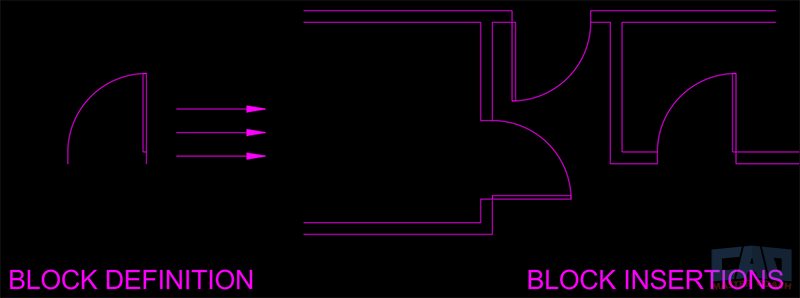
This distinction is critical because changes happen at the definition level, not the insertion level. For example, if you move or scale one insertion, only that instance changes. But if you redefine the block definition itself, every insertion updates automatically.
1.5 Benefits Beyond Efficiency
While time savings are the obvious benefit, blocks also:
- Reduce errors: Fewer chances for misalignment or inconsistent geometry.
- Standardize symbols: Ensure team-wide consistency.
- Support data-driven workflows: With attributes, blocks can hold information like part numbers or equipment tags.
- Enable automation: Advanced CAD standards and BIM workflows often depend on blocks.
1.6 Common Misconceptions
Beginners sometimes think blocks are only for symbols or small details, but in practice, blocks can represent almost anything—from a single chair, to an entire floor plan, or the title block. Another misconception is that once you create a block, it can’t be changed. In reality, AutoCAD provides powerful tools like the Block Editor (BEDIT) that let you update and enhance blocks at any time.
1.7 Why Understanding Blocks is Essential
If you want to move from being a casual AutoCAD user to a professional-level drafter or designer, you can’t skip blocks. Blocks form the foundation for more advanced features like dynamic blocks, annotative scaling, and even external references (Xrefs). Think of blocks as the bridge between basic drafting and professional CAD management.
Section 2: Creating a Simple Block
Creating your first block in AutoCAD may feel intimidating at first, but the process is straightforward once you understand the steps. By mastering simple blocks, you’ll unlock the foundation for everything from reusable symbols to complex dynamic components. This section will walk you through the workflow of creating a block, highlight best practices, and cover the common pitfalls beginners often face.
2.1 The Concept of a Simple Block
A simple block is the most basic type of block you can create in AutoCAD, and has four properties:
- Geometry: The objects you’ve drawn (lines, arcs, circles, text, etc.).
- Base point: The reference point used to insert the block.
- Name: A unique identifier for the block definition.
- Insertion units: The scale AutoCAD uses when placing the block in different drawings.
Once these are defined, you can insert the block repeatedly into your drawing, each time creating a new “instance” of that definition.
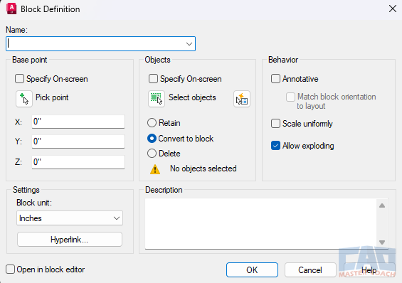
2.2 Step-by-Step Workflow
Here’s a step-by-step breakdown of how to create a simple block in AutoCAD:
1. Draw your geometry
- Start by drafting the object you want to turn into a block. For example, a standard office chair or a door symbol.
- Make sure it’s drawn cleanly and at full scale (1:1).
2. Choose the BLOCK command
Type BLOCK in the command line or go to the Insert tab → Block Definition panel → Create Block.
This opens the Block Definition dialog box.
Go here for a deep dive into the BLOCK Command.
3. Give the block a name
- Enter a unique, descriptive name like A-CHAIR-STD or A-DOOR-SINGLE.
- Avoid vague names like “Block1” or “Test,” as they’ll create confusion later.
4. Select the base point
- Pick a logical insertion point. For example:
- - The hinge point of a door.
- - The back-left corner of a desk.
- - The center point of a circular table.
- The base point ensures consistency every time you insert the block.
5. Select objects
- Choose the objects that make up your block.
- Confirm you’ve selected everything needed—lines, arcs, hatches, and even text if applicable.
6. Define insertion units
- Set the block units (inches, millimeters, feet, etc.).
- This ensures the block scales correctly when inserted into drawings with different units.
7. Save the block definition
- Click OK, and AutoCAD will create the block definition in your current drawing.
- Your original geometry may remain or be converted into the block depending on your settings.
2.3 Example: Creating a Door Block
Let’s put this into practice:
- Draw a single-line representation of a 3-foot-wide door and its swing arc.
- 1. Draw a vertical line 6” tall
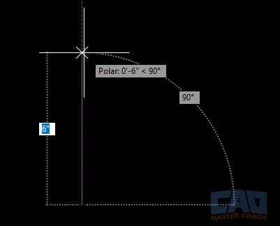
2. Offset that line 36” to the right

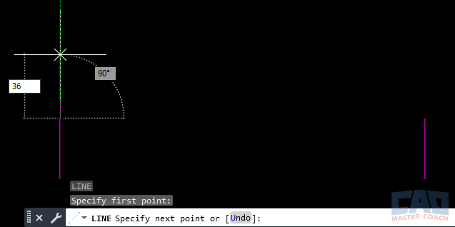
3. Draw another vertical line beginning from the top of the first line and extend up 36” in the Y direction
4. Draw an arc. Use the START CENTER END option in the ribbon menu. Select the top of the 6” line at the right of the doorway as the START. Select the top of the 6” line at the left of the doorway (the first line that was drawn) as the CENTER. Select the top of the 36” long line as the END. An arc is drawn that is the sweep of the door.
Take a deep dive into the ARC Command here.
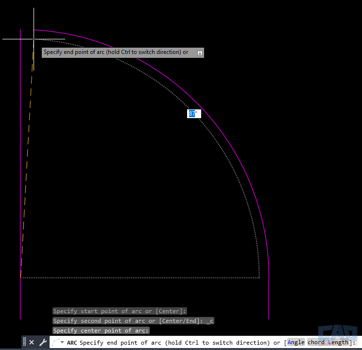
5. Start the BLOCK command and name it A-DOOR-36.
See more about the BLOCK command here.
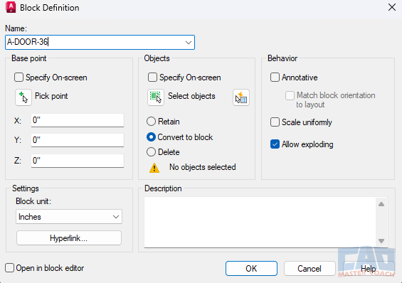
6. Choose the hinge point as the base point.
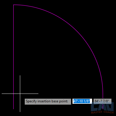
7. Select the line, arc, and door panel geometry.
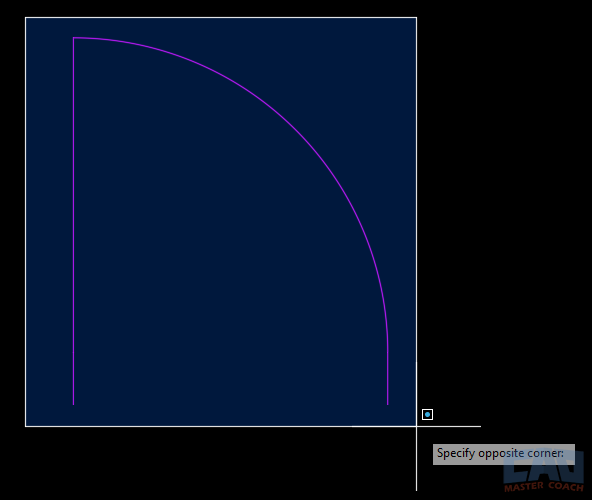
8. Set units to inches.
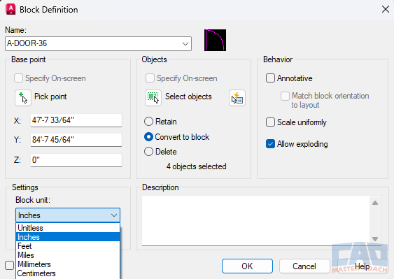
9. Press OK to Save the block.
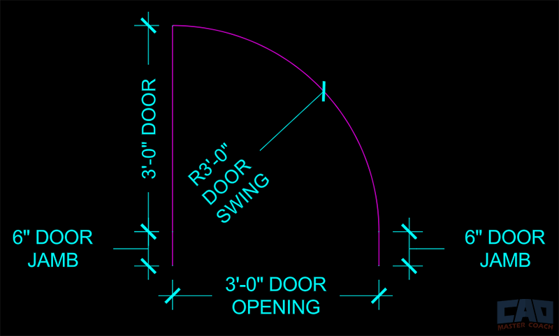
Note that all of the individual drawing objects are dimensioned in the image above.
The finished block named A-DOOR-36 looks like this:
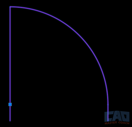
Notice there is only one snap point in the finished block, and it is at the hinge point of the door, as we selected. AutoCAD treats the entire block as one drawing object. Now, every time you need a 3-foot-wide door, you can simply insert this block instead of redrawing it.
2.4 Common Pitfalls for Beginners
Many new users run into issues when creating blocks. Here are the most common mistakes and how to avoid them:
- Forgetting to specify a logical base point: Without a logical base point, your block will be awkward to place. Always think about how it should “snap” into your drawing.
- Using vague names: If you name your block “Block1,” you’ll quickly lose track. Use descriptive, standard naming conventions.
- Mixing units: Drawing geometry in inches but defining the block as millimeters leads to scaling nightmares. Always check INSUNITS.
- Not cleaning geometry: If your geometry has overlapping lines, stray endpoints, or unjoined polylines, your block will be messy and unreliable.
2.5 Best Practices for Simple Blocks
- Draw at 1:1 scale: Always model objects at their real-world size. Scaling happens during insertion, not creation.
- Use layers wisely: Geometry inside a block should be on logical layers (e.g., A-FURN). Don’t leave everything on Layer 0 unless it’s intentional.
- Layer 0: All objects placed on Layer 0 in a block will inherit the properties of the layer the block is being inserted on. This can be useful, or it can be a hinderance, depending on the block and the drawing. Keep this in mind when creating blocks.
- Test insertion: After creating the block, insert it once or twice to confirm that the base point, scale, and orientation feel correct.
- Think about reuse: Even simple blocks should be designed with reuse in mind. Consider if this object could work in other projects or be part of a larger library.
2.6 Why Simple Blocks Matter
Creating simple blocks is a great way to get started building your library. Simple blocks may not have the flexibility of dynamic blocks or attributes, but they form the building blocks (pun intended) of your library. Once you’re comfortable creating simple blocks, you’ll find it easier to move into advanced techniques later. Think of this step as learning how to use a hammer before you move on to power tools—fundamental, reliable, and always useful.
Section 3: Best Practices for Block Naming
One of the most overlooked aspects of creating blocks in AutoCAD is naming. While it may seem like a small detail, how you name your blocks has a massive impact on project efficiency, consistency, and collaboration. Poorly named blocks lead to confusion, duplication, and wasted time. On the other hand, a strong naming convention creates clarity and makes your block library easy to use both for you and for your team.
3.1 Why Naming Matters
Imagine opening a drawing file and finding a block called “Block1.” What does that tell you? Nothing. It could be a chair, a door, a window, or a structural column. Now imagine a file filled with dozens of vague names like “Block2,” “Block3,” and “Test.” Not only is this frustrating, but it also makes it impossible to know what you’re working with.
Proper naming conventions provide:
- Clarity: You know exactly what the block represents before you insert it.
- Efficiency: Searching for blocks becomes faster when names are consistent and descriptive.
- Scalability: As your block library grows, proper names prevent chaos.
- Team collaboration: Colleagues can understand and use your blocks without asking for clarification.
A strong block name turns a mysterious symbol into a clearly defined tool.
3.2 Structure of a Good Block Name
A recommended structure is:
Discipline – Category – Type/Size
This structure mirrors common CAD standards and works across industries.
Examples:
- A-DOOR-36 → Architectural, door, 36" wide.
- A-WINDOW-DOUBLE → Architectural, double window.
- E-OUTLET-GFCI → Electrical, GFCI outlet symbol.
- M-DUCT-12x8 → Mechanical, duct size 12"x8".
By using this three-part system, you keep names short but meaningful. The prefix identifies the discipline, the middle identifies the category, and the suffix specifies the type, size, or variation.
3.3 Common Discipline Codes
Here are some widely used discipline codes you can adapt:
- A = Architectural
- C = Civil
- E = Electrical
- M = Mechanical
- P = Plumbing
- S = Structural
Using these codes ensures that anyone familiar with industry standards can navigate your block library.
3.4 Avoiding Duplication
One of the biggest problems in unmanaged block libraries is duplicate blocks with slightly different names. For example:
- Chair
- Chair1
- Chair Final
- Chair_Final2
These clutter your library and cause users to waste time guessing which one is correct. To avoid this:
- Establish a single master library for approved blocks.
- Use clear naming conventions from the start.
- Document the rules in a PDF or company standards manual.
- Audit your library periodically to eliminate duplicates.
3.5 Tips for Team Environments
When working in a team, consistency matters even more. Multiple drafters may create blocks for the same project, and without agreed-upon standards, your library will quickly devolve into chaos.
Best practices for teams include:
- Shared library: Store blocks on a network drive or cloud-based repository.
- Naming guide: Provide every team member with the same naming convention document.
- Approval process: New block names should be reviewed before being added to the library.
- Training: Ensure new employees are trained in block naming conventions.
When the whole team follows the same system, drawings remain consistent, and collaboration becomes seamless.
3.6 Real-World Example
Let’s consider a midsize architecture firm. Without a standard, one drafter creates a block called “Window1,” another makes “DoubleWindow,” and a third inserts “Win.” Over time, the same symbol appears with multiple names, confusing both the CAD team and the contractors who rely on the drawings.
By switching to a standard like A-WINDOW-DBL-48, everyone uses the same name for the same item. Searching for windows in the block list becomes easy, and no one wastes time inserting or redefining duplicate blocks.
3.7 Final Thoughts
Naming blocks may not feel glamorous, however, it is one of the most important habits you can build in AutoCAD. Clear, consistent, and descriptive block names save time, prevent errors, and keep your library organized. Whether you’re working solo or as part of a large team, adopting a professional naming convention pays off every single day you use AutoCAD.
Get the Top 35 AutoCAD Commands for FREE
Section 4: Using Attributes in Blocks
While simple blocks are powerful, adding attributes takes them to another level. Attributes allow you to embed text fields inside blocks that carry information, making them more than just geometry. They transform blocks from mere symbols into smart, data-driven objects.
Whether you want to label furniture with model numbers, tag equipment with unique IDs, or build a title block that automatically updates project information, attributes are the key.
4.1 What are Block Attributes?
A block attribute is a text-based property that you define when creating a block. Unlike ordinary text, attributes are dynamic and editable each time you insert the block.
For example:
- A furniture block could include an attribute for “Manufacturer” and “Model Number.”
- An outlet symbol block could include “Circuit Number.”
- A title block could have attributes for “Project Name,” “Drawing Number,” and “Date.”
These attributes can later be extracted into a table or exported to a database, giving you a powerful way to manage drawing information.
4.2 Why Attributes Matter
The value of attributes comes down to three main advantages:
- Efficiency – Instead of manually typing repetitive notes, attributes allow you to standardize inputs.
- Accuracy – When you redefine or update attributes, they stay linked to the block, reducing chances for inconsistency.
- Data integration – Attributes can be exported to schedules, spreadsheets, or databases for reporting purposes.
In other words, attributes turn AutoCAD from just a drafting tool into a lightweight Building Information Modeling (BIM) tool.
4.3 How to Add Attributes
Adding an attribute to a block is straightforward. The process uses the ATTDEF command (Attribute Definition):
- Type ATTDEF or find it under the Insert tab → Block Definition panel → Define Attributes.
- Fill out the Attribute Definition dialog box:
- Tag: The name of the attribute (e.g., DOOR_NUM).
- Prompt: What AutoCAD asks the user when inserting the block (e.g., “Enter Door Number:”).
- Default: A prefilled value (e.g., 101).
- Place the attribute in your geometry.
- Save the geometry and attribute together as a block using the BLOCK command.
Now, whenever you insert that block, AutoCAD will prompt you to enter a unique value for the attribute.
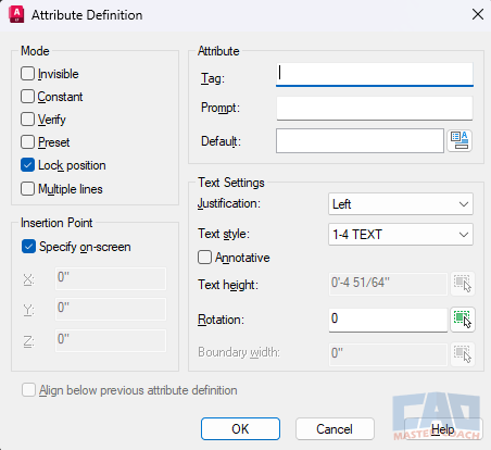
4.4 Practical Use Cases
Attributes are versatile and can be applied across disciplines:
Architecture:
- Room tags with room numbers.
- Door blocks with door IDs.
- Furniture blocks with manufacturer and model.
Engineering:
- Electrical outlet symbols with circuit numbers.
- Lighting fixtures with wattage or type.
- Mechanical equipment with horsepower ratings.
- Columns tagged with the size
Project Documentation:
- Title blocks with project name, drawing number, and revision date.
- Sheet numbers that update automatically.
By embedding this metadata directly into the drawing, you keep your information organized and linked to your geometry.
4.5 Editing Attributes
Sometimes you’ll need to modify attributes after the block has been inserted. AutoCAD provides several tools for this:
- EATTEDIT: Edit individual attribute values inside a block.
- BATTMAN: (Block Attribute Manager): Manage attributes for a block definition.
- ATTEDIT: Quickly edit attribute text without exploding the block.
These commands give you flexibility while preserving the integrity of the block definition.
4.6 Extracting Attributes
One of the most powerful features of attributes is data extraction. AutoCAD can pull attribute data from blocks and compile it into a table inside your drawing or export it to Excel.
For example, if you’ve created furniture blocks with attributes for manufacturer and model, you can extract all instances into a furniture schedule automatically. This eliminates manual counting and reduces errors in documentation.
4.7 Common Mistakes with Attributes
- Using vague tags: Tags like “DATA1” don’t explain the purpose. Use descriptive names (e.g., CIRCUIT_NUM).
- Overloading attributes: Too many attributes make blocks cumbersome. Stick to essential fields.
- Forgetting defaults: Always set defaults for consistency, even if users overwrite them later.
- Exploding attribute blocks: This breaks the link and removes intelligence—avoid it unless absolutely necessary.
4.8 Final Thoughts
Attributes elevate blocks from static geometry to intelligent objects. They allow you to merge drafting with data management, making your AutoCAD drawings both visually clear and information-rich. For small projects, attributes can speed up labeling. For large projects, they provide a foundation for schedules and reporting.
Mastering attributes is a key step toward building smarter, more efficient CAD workflows—and once you’ve used them effectively, you’ll wonder how you ever managed without them.
Section 5: Scaling and Units
Scaling and units may not sound like the most exciting topic in AutoCAD; however, they are absolutely critical when working with blocks. Many people experience frustrations with blocks—objects appearing too big or too small, symbols not matching the drawing scale, or geometry inserting incorrectly. Much of this stems from misunderstanding how scaling and units interact. A well-made block should insert seamlessly into any drawing, regardless of units or viewport scale.
5.1 Why Scaling Matters
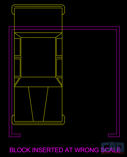
When you create a block, AutoCAD stores its insertion units as part of the block definition. This ensures the block inserts at the correct size, whether your drawing is set up in inches, feet, millimeters, or meters. If you ignore this setting, you may end up with mismatched blocks: a chair drawn in inches might appear 25.4 times too large in a millimeter-based drawing, or a symbol meant to be one foot tall may shrink to almost nothing in a metric project.
Scaling also matters when plotting. If text, dimensions, and symbols are not scaled properly, they may look fine in model space and appear unreadable or inconsistent in paper space.
5.2 Draw at 1:1 Scale
One of the most important rules in AutoCAD is to always draw at full size (1:1). If a dining table is 60 inches wide in the real world, you should draft it as 60 units wide in your drawing. This applies regardless of whether you’re using imperial or metric units.
Blocks should also always be created at full size. Insertion scaling, not creation scaling, is how you control their display size.
5.3 Insertion Units and INSUNITS
AutoCAD uses a system variable called INSUNITS to determine the units for block insertion. When you create a block, you can assign units such as inches, millimeters, or feet. When inserting the block into another drawing, AutoCAD will scale it automatically to match the target drawing’s units.
For example:
- If a block is defined in inches and inserted into a drawing set to millimeters, AutoCAD scales it by 25.4.
- If a block is defined in meters and inserted into a drawing set to feet, AutoCAD scales accordingly.
This automatic scaling prevents errors, but only if you set the units correctly in the first place. Forgetting this step is one of the top reasons blocks insert incorrectly.
5.4 Annotative Scaling vs. Manual Scaling
Another layer of complexity arises with text, dimensions, and symbols. AutoCAD offers two main approaches:
- Manual scaling: You manually adjust the text height or symbol size for each viewport scale. For example, if your text is 3/32” tall at 1/8”=1’-0”, you must scale it up for a 1/4” detail view. This traditional method works but is time-consuming.
- Annotative scaling: AutoCAD automatically adjusts the size of annotative objects (like text, dimensions, and some symbols) based on the viewport scale. This ensures consistent appearance across different scales without manual adjustments.
When designing blocks, you must decide whether to rely on manual or annotative scaling. Many offices still prefer manual scaling for blocks, especially for geometry-heavy objects, but annotative scaling is a powerful option for symbols and annotation-based blocks.
5.5 Avoiding Scaling Problems
Here are some tips to prevent scaling headaches:
- Set INSUNITS properly – Always define the insertion units when creating blocks.
- Test insertions – Insert the block into a fresh drawing with known units to confirm it behaves as expected.
- Separate libraries by system – If your office works in both imperial and metric, consider maintaining two separate block libraries.
- Use consistent standards – Agree on text heights, symbol sizes, and lineweights before building blocks, so everything scales consistently when plotted.
- Be careful with nested blocks – A block that contains other blocks may inherit scaling issues if its nested components use different units.
5.6 Real-World Example
Imagine an architect working on a U.S. project in inches who imports a block library from a European consultant. The consultant’s furniture blocks were drawn in millimeters. If the architect doesn’t set insertion units, every desk may come in 25.4 times too large, requiring hours of cleanup. By setting INSUNITS correctly, AutoCAD would automatically convert millimeters to inches, saving significant time and frustration.
5.7 Final Thoughts
Scaling and units might feel like background settings, but they are the foundation of reliable block workflows. A block that looks perfect in one drawing but inserts incorrectly in another is not a good block, it’s a liability. By committing to drawing at 1:1, defining insertion units, and understanding annotative vs. manual scaling, you’ll ensure that your blocks are not only
Section 6: Editing & Updating Blocks
Creating blocks is only the beginning. Over the life of a project—or across multiple projects—you’ll often need to edit or update blocks. Maybe the client changed the furniture size, the symbol standard was revised, or a mistake needs correcting. The good news is that AutoCAD provides flexible ways to update blocks while preserving consistency. Knowing when to use each method is essential for maintaining a clean, professional block library.
6.1 Exploding vs. Editing
Many beginners believe that the only way to modify a block is to explode it, edit the geometry, and then remake it. While exploding works in a pinch, it’s usually a bad habit for three reasons:
- Loss of intelligence – Once a block is exploded, it becomes loose geometry again. It loses its name, attributes, and connection to the definition.
- Inconsistency – Editing one exploded copy won’t update the other instances. You’ll have to hunt down every copy manually.
- Clutter – Exploded geometry increases file size and decreases efficiency.
Instead, the better approach is to edit the block definition directly.
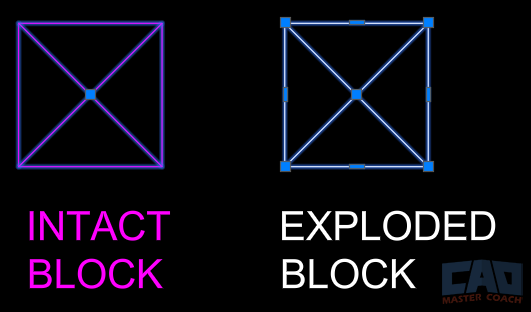
Notice in the image above the intact block on the left has one grip and is the color of the layer the block is on compared to the exploded block on the right has grips for every line that comprises the original block. Exploding a block breaks it down to the elements the block is made of.
6.2 Block Editor (BEDIT Command)
The Block Editor is AutoCAD’s dedicated environment for editing blocks. Here’s how it works:
- Type BEDIT in the command line.
- Select the block you want to edit from the Edit Block Definition window that appears.
- AutoCAD opens the block in a separate editing space. When the Block Editor is active, the background of the screen is grey and the ribbon menus change to the Block Editor Ribbon. See the BLOCK Command for more information.
- Make changes: add, delete, or modify geometry.
- Close the Block Editor and save changes.
The benefit of BEDIT is that your changes apply to the block definition itself. That means every instance of the block in your drawing updates automatically—saving hours of manual editing.
6.3 Redefining Blocks
Another way to update a block is to redefine it. If you create a new block with the same name as an existing one, AutoCAD asks if you want to redefine the block. Choosing Yes replaces the old definition with the new one across your drawing.
This method is especially useful when you maintain a master library. You can update the block in the library file and then insert it into your drawing. AutoCAD will recognize the name, prompt to redefine, and update all instances.
Example:
Let’s say you have a block named A-CHAIR-STD. You realize the seat width is incorrect. You edit the chair block in your library file, then reinsert it into your project. AutoCAD asks, “Block already defined. Redefine it?” Once you confirm, every chair in the project updates instantly.
6.4 Attribute Updates
When working with blocks that contain attributes, editing can be slightly more complex. For example, if you add a new attribute to a title block, existing instances won’t automatically show the new field. In this case, you may need to use:
- ATTSYNC command – Synchronizes block instances with updated attributes.
- BATTMAN (Block Attribute Manager) – Allows you to manage, reorder, and rename attributes within a block.
This ensures that all existing insertions reflect your updated definition.
6.5 Best Practices for Editing
- Edit the definition, not insertions – Always aim to update the block definition so changes propagate across the project.
- Keep a master library – Store block definitions in a dedicated file or folder. Edit blocks there, not in random project files.
- Test edits in a sandbox drawing – Before redefining blocks in a critical project, test the changes in a separate file to avoid unexpected issues.
- Version your blocks – For major updates, consider renaming the block (e.g., A-CHAIR-STD-V2) to preserve older versions for reference.
- Document changes – If working in a team, communicate when a block definition has been updated so everyone knows to reinsert the new version.
6.6 Real-World Application
Consider an architectural firm working on a multi-building project. The electrical outlet symbol was initially created with a circle, but later the client requests a square outline instead. Rather than redrawing hundreds of outlets, the drafter edits the block definition in the Block Editor and saves. Instantly, every outlet symbol updates across multiple drawings. What could have taken days manually is resolved in minutes.
6.7 Final Thoughts
Editing and updating blocks is just as important as creating them. Exploding should be a last resort, not a standard practice. By leveraging the Block Editor, redefining blocks, and managing attributes properly, you maintain efficiency, consistency, and professionalism in your CAD work. Over time, this discipline builds a library of blocks that evolves with your standards and remains a valuable asset for every project.
Section 7: Organizing a Block Library
A well-crafted block is only as useful as your ability to find and reuse it. As you continue creating blocks for doors, windows, furniture, symbols, and equipment, your collection will quickly grow. Without organization, your library can spiral into chaos, leaving you with duplicate blocks, unclear names, and wasted time. A thoughtfully organized block library ensures that your work is accessible, efficient, and scalable across projects and team members.
7.1 Why Organization Matters
Imagine you’ve drawn a perfect set of furniture blocks—desks, chairs, and tables—but saved them in random files with inconsistent names. Months later, you need that desk again. Do you redraw it from scratch? Look through dozens of project folders and try to remember which project you drew that block for? Or, do you ask your teammates if they remember which project you drew a specific block for (hint: they probably don’t). This kind of inefficiency is common in offices without a block library.
Organizing your blocks properly:
- Saves time by making blocks quick to locate and insert.
- Prevents duplication by ensuring you know what already exists.
- Improves collaboration by giving team members a consistent resource.
- Increases professionalism by maintaining drawing standards.
Your block library should be thought of as an investment. The more structured your block library is, the more valuable it becomes.
7.2 File Structure Options
There are two main strategies for storing blocks:
Flat Folder Structure
All blocks are kept in one central folder. This is simple but becomes harder to navigate as your collection grows. Flat folders work best for small, personal libraries with fewer than 50 blocks.
Categorized Folder Structure
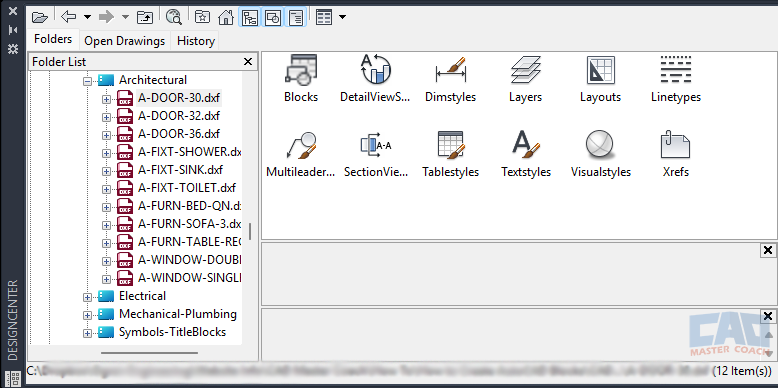
Blocks are sorted into discipline- or function-based folders. For example:
- /Architectural → doors, windows, furniture, fixtures.
- /Electrical → outlets, switches, panels, lighting symbols.
- /Mechanical → ducts, equipment, valves.
- /Title Blocks & Symbols → sheet borders, north arrows, section cuts.
This method requires more setup but is far more scalable for larger libraries or teams.
7.3 Naming Conventions
Good file organization pairs with strong naming conventions (covered in Section 3). For block libraries, filenames should mirror the internal block names whenever possible. For example:
- File: A-DOOR-36.dwg → Block: A-DOOR-36
- File: E-OUTLET-GFCI.dwg → Block: E-OUTLET-GFCI
This consistency ensures that when you browse your folders, you immediately know what each block contains.
7.4 Tool Palettes
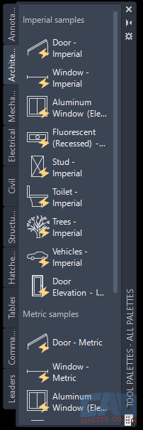
AutoCAD’s Tool Palettes are one of the best ways to organize and deploy blocks. They allow you to:
- Create drag-and-drop icons for each block.
- Group blocks into palettes by discipline or project type.
- Add previews and descriptions for easier identification.
For teams, palettes can be shared across a network. When a new block is added or updated in the palette, everyone has access immediately. This reduces guesswork and keeps projects consistent.
7.5 Libraries for Teams
When working in a team environment, block libraries should be centralized and standardized. Best practices include:
- Shared network drive or cloud location – Ensure all team members pull blocks from the same source.
- Read-only permissions – Limit editing rights so only designated CAD managers can update the master library.
- Approval process – New blocks should be reviewed before being added, preventing duplicates and maintaining quality.
- Training sessions – Teach team members how to navigate and use the library efficiently.
A centralized Block library is one of the best ways to elevate CAD standards in a professional office.
7.6 Tips for Maintenance
Building a library is not a one-time task; it requires ongoing care. Some maintenance tips include:
- Regular audits – Check for duplicates, outdated standards, or unused blocks.
- Version control – Keep backups of older block versions in case they’re needed.
- Documentation – Maintain a simple PDF guide that explains naming conventions, folder structures, and usage rules.
- Growth planning – Organize folders with expansion in mind, so you don’t need to reorganize every few months.
7.7 Final Thoughts
An organized block library transforms AutoCAD from a drawing tool into a design ecosystem. Instead of wasting time hunting for symbols or redrawing geometry, you can focus on design and productivity. Whether you’re a solo drafter building a small personal collection or a CAD manager overseeing a large team, investing in an organized library pays off every time you start a new project.
Get the Top 35 AutoCAD Commands for FREE
Section 8: Advanced Block Techniques
Once you’ve mastered simple blocks and attributes, you can take your AutoCAD skills to the next level with advanced block techniques. These methods transform blocks from static, repetitive objects into flexible, intelligent tools that adapt to different situations. The most important advanced techniques are dynamic blocks, visibility states, and parametric blocks. Together, these tools reduce the number of separate block definitions you need while giving you incredible control over your drawings.
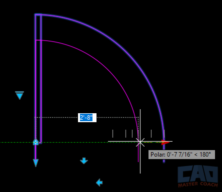
8.1 Dynamic Blocks
A dynamic block is a block with built-in flexibility. Instead of making separate blocks for every variation of an object, you create one dynamic block that can stretch, flip, rotate, or change size on demand.
Common Dynamic Block Features:
- Stretch actions: Adjust the size of an object, like resizing a desk or lengthening a beam.
- Flip actions: Mirror the block without creating a separate “left” and “right” version.
- Rotation actions: Rotate parts of the block, useful for symbols or angled geometry.
- Array actions: Add or remove repetitive elements, such as chairs around a table.
Example: Instead of creating four separate blocks for left-hand doors, right-hand doors, 30-inch doors, and 36-inch doors, you could create one dynamic door block. With stretch and flip actions, it can adjust to any width or swing direction.
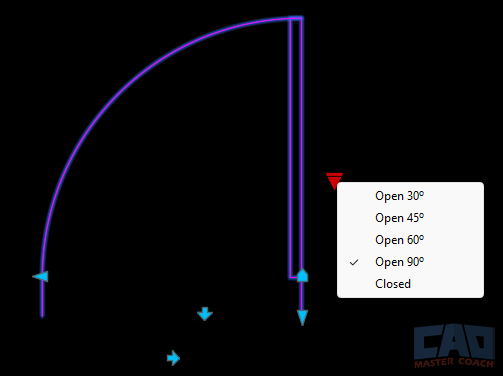
Dynamic blocks save file space, reduce library clutter, and give you unmatched flexibility.
8.2 Visibility States
Visibility states allow a single block to display multiple variations without redefining the geometry each time.
Examples of Visibility States:
- A single electrical outlet block with multiple symbols: standard duplex, GFCI, and 220V.
- A structural steel block that can toggle between wide flange, channel, and angle shapes.
- A furniture block with “with arms” and “without arms” options.
The benefit is efficiency: you insert one block and simply switch visibility states as needed. This reduces duplication in your library while keeping drawings neat and consistent.
8.3 Parametric Blocks
Parametric constraints take dynamic blocks even further by applying rules to geometry. With parametrics, you can control dimensions, angles, and relationships between objects inside a block.
Examples of Parametric Behavior:
- A window block where the glass area always stays centered within the frame, no matter the width or height.
- A rectangular duct block that maintains a fixed aspect ratio.
- A stair block where tread depth and riser height remain proportional when stretched.
Parametric blocks introduce a level of “intelligence” into your drawings. They don’t just stretch—they behave logically based on your design rules.
8.4 When to Use Advanced Blocks
While advanced techniques are powerful, they should be used strategically. Dynamic and parametric blocks take more time to set up than simple blocks, so ask yourself:
- Will this object be reused often? (e.g., doors, windows, symbols).
- Does this object have multiple common variations?
- Would a single smart block reduce confusion and clutter in the library?
If the answer is yes, advanced blocks are worth the effort.
8.5 Common Pitfalls
- Overcomplication: Adding too many actions can make blocks confusing to use. Keep it simple.
- Performance issues: Extremely complex dynamic blocks may slow down large drawings.
- Lack of training: Team members may not understand how to manipulate dynamic features without guidance.
To avoid problems, always test your advanced blocks thoroughly and provide instructions if they’re part of a shared library.
8.6 Final Thoughts
Advanced block techniques elevate AutoCAD from a basic drafting tool to a smart design platform. With dynamic, visibility, and parametric blocks, you can drastically reduce the size of your library while increasing its power. Instead of dozens of variations cluttering your files, you’ll have a handful of versatile, intelligent blocks that adapt to any situation.
Mastering these techniques may take some time, but once you incorporate them into your workflow, you’ll wonder how you ever worked without them.
Section 9: Real-World Examples
Now that we’ve covered how to create, edit, and enhance blocks, let’s step back and look at how they’re actually used in practice. Blocks aren’t just abstract CAD tools—they’re the backbone of drafting standards in almost every discipline. Whether you’re an architect, engineer, or contractor, blocks streamline your workflow and ensure consistency across projects. This section explores how different industries apply blocks and why they’re indispensable in real-world scenarios.
9.1 Architectural Applications
Architecture is one of the heaviest users of blocks. In architectural drawings, blocks appear in almost every plan, section, and detail.
Common Architectural Blocks:
- Doors and Windows: Standardized widths, swing directions, and types (single, double, sliding).
- Furniture: Chairs, desks, tables, beds, and sofas.
- Fixtures: Toilets, sinks, showers, and kitchen equipment.
- Symbols: Section cuts, north arrows, detail callouts, and sheet references.
- Title Blocks: Company-branded sheets with attributes for project name, drawing number, and revision.
Example: An architect drafting a floor plan might insert dozens of identical 36-inch-wide doors. With blocks, all doors look identical and can be updated in one step if the design changes. The same applies to fixtures—if a bathroom sink specification changes, the block can be redefined to reflect the new fixture across every plan.
9.2 Mechanical, Electrical, and Plumbing (MEP) Applications
MEP engineers also rely heavily on blocks, particularly for symbols and equipment layouts.
Mechanical Blocks:
- HVAC equipment (fans, chillers, VAV boxes).
- Ductwork fittings.
- Diffusers and grilles.
Electrical Blocks:
- Outlets (duplex, GFCI, specialty).
- Switches (single-pole, three-way, dimmer).
- Lighting fixtures.
- Panelboards and transformers.
Plumbing Blocks:
- Pipes and valves.
- Water heaters.
- Sanitary fixtures.
Example: An electrical engineer working on a hospital might use hundreds of outlet symbols across multiple sheets. Instead of redrawing, they insert a block. If the outlet style needs to change—say from duplex to GFCI—they can update the block definition once, and every symbol updates instantly.
9.3 Civil Engineering Applications
Civil engineers apply blocks in both 2D drafting and site layout drawings.
Common Civil Blocks:
- Manholes and catch basins.
- Utility markers (gas, water, electrical).
- Roadway elements (curbs, traffic signs, guardrails).
- Trees and landscape elements.
Example: In a subdivision plan, each lot might need utility connection symbols. Instead of drawing each by hand, civil engineers place blocks. If the symbol standard changes (say, the city adopts a new manhole symbol), the block library is updated once, and all drawings can be synchronized.
9.4 Structural Engineering Applications
Structural drawings also benefit from standardized blocks.
Common Structural Blocks:
- Steel profiles (wide flange, angle, channel).
- Rebar symbols.
- Foundation piers and footings.
- Grid bubbles and section markers.
Example: A structural engineer working on a high-rise might use grid bubbles across dozens of sheets. Each bubble is a block with an attribute for grid number. If the bubble style changes, the block is redefined once, and every sheet reflects the update.
9.5 Contractor and Construction Applications
Even contractors use blocks to communicate construction intent, often in shop drawings or coordination models. Blocks keep drawings consistent and make it easy to recognize critical information at a glance.
Common Contractor Blocks:
- Equipment layouts.
- Safety symbols.
- Detail callouts.
- Legend items.
9.6 Why Blocks are Universal
Across all disciplines, blocks serve the same fundamental purposes:
- Speed: Faster drafting and fewer repetitive tasks.
- Consistency: Uniform symbols across drawings and sheets.
- Accuracy: Updates happen globally, reducing mistakes.
- Standards: Industry and company standards are maintained effortlessly.
9.7 Final Thoughts
The power of blocks isn’t limited to one discipline—they’re universal tools that every CAD professional relies on. From architectural door swings to electrical outlets to civil utility markers, blocks bring order and efficiency to complex projects. Once you start building and using a consistent block library, you’ll notice a dramatic improvement in your workflow, accuracy, and professional presentation.
Section 10: Seven Common Mistakes to Avoid When Creating Blocks
Blocks are a powerful tool in AutoCAD, but like any tool, they can be misused. Many AutoCAD users, especially beginners, fall into habits that undermine the advantages of blocks. Instead of saving time and improving consistency, poorly made or poorly managed blocks can lead to wasted effort, confusion, and even project errors. By understanding the most common mistakes, you can avoid them and ensure that your block library remains a reliable asset instead of a liability.
10.1 Not Setting a Correct Base Point
The base point is the reference point used when inserting a block. Choosing the wrong base point is one of the most common errors.
- Example: If you create a chair block and set the base point in the middle of the seat, it will be difficult to align against walls or desks. Instead, the back corner of the chair would make a better base point.
- Consequence: Every time you insert the block, you’ll waste time aligning it. Inconsistent alignment also causes messy drawings.
10.2 Forgetting to Define Units
Blocks rely on insertion units to scale properly between drawings. If you forget to set units, a block drawn in inches might insert at the wrong size in a metric drawing—or vice versa.
- Example: A toilet block drawn in millimeters may appear 25.4 times larger when inserted into an imperial drawing.
- Consequence: Hours wasted resizing blocks or redrawing geometry.
10.3 Overusing Explode
Many drafters habitually use EXPLODE on blocks before editing them. While this may feel like the fastest way to make changes, it destroys the block’s intelligence.
- Problem: Once exploded, the geometry is no longer linked to the block definition.
- Consequence: You lose the ability to update all instances at once, defeating the entire purpose of blocks.
10.4 Storing Geometry on the Wrong Layer
A classic mistake is placing all block geometry on Layer 0 or, worse, on a random layer.
- Layer 0 rule: Geometry drawn on Layer 0 will adopt the layer properties of the layer it’s inserted on. This is useful for symbols like doors or furniture.
- However: Not all geometry should be on Layer 0. For example, a title block should retain its lineweights and colors regardless of the insertion layer.
10.5 Poor Naming Practices
Blocks named “Block1,” “Test,” or “Chair2” cause confusion. Without a standard naming system, your library quickly fills with duplicates and inconsistencies. This causes confusion and wastes the very time creating a block was intended to save.
- Problem: You may not know which block is correct, or you might create unnecessary duplicates.
- Consequence: Wasted time and potential drafting errors.
10.6 Overcomplicated Blocks
Advanced features like dynamic actions and parametric constraints are powerful—but they can also be overused. A block that tries to do too much can confuse users and slow down drawings.
- Example: A door block with dozens of visibility states and parametric rules may be difficult for a junior drafter to use.
- Consequence: Frustration, errors, and slower performance in large files.
10.7 Copying Blocks from Old Projects
It’s tempting to grab a block from an old drawing rather than insert one from the library. The problem is that old projects often contain outdated, messy, or inconsistent blocks.
- Consequence: Standards drift, and you end up with multiple versions of the same symbol floating around.
10.8 Final Thoughts
Blocks are designed to make life easier, but misuse can create the opposite effect. By setting logical base points, defining units, avoiding unnecessary exploding, managing layers correctly, naming blocks consistently, keeping blocks simple, and relying on a centralized library, you’ll avoid the most common pitfalls. Good block habits don’t just improve your current drawing, they ensure smoother, faster, and more professional projects for years to come.
Section 11: Building Your First Block Library
By now, you understand how blocks work, why they matter, and how to create and manage them effectively. But theory is only useful if it translates into practice. That’s where a block library comes in. Building your own block library ensures you always have a reliable set of reusable symbols at your fingertips. This section walks you through what to include, how to build it, and how to set it up for long-term success.
11.1 Why Create a Block Library?
Think of your block library as your CAD toolbox. Every time you begin a project, you don’t want to reinvent the wheel by redrawing furniture, doors, or symbols. A block library gives you a curated library of the most common, essential blocks you can drop into any new drawing.
The benefits include:
- Time savings: No more redrawing basic geometry.
- Consistency: Every project starts with the same symbols and standards.
- Professionalism: A well-organized pack reinforces your design credibility.
- Scalability: You can expand your block library as your needs grow.
11.2 What to Include in Your Block Library
Your block library should reflect your discipline and the types of projects you typically work on. At minimum, consider including:
For Architecture:
- Doors: 30”, 32”, and 36” swing doors (left- and right-hand).
- Windows: Standard double and single casement.
- Furniture: Desk, chair, bed, sofa, table.
- Fixtures: Toilet, sink, bathtub, shower.
- Symbols: Section cut, elevation marker, north arrow.
- Title Block: Branded sheet with attributes for project info.
For Mechanical Engineering (MEP):
- Electrical Outlets: Duplex, GFCI, 220V.
- Switches: Single-pole, three-way, dimmer.
- Mechanical Equipment: Diffuser, VAV box, fan symbol.
- Plumbing Symbols: Valve, water heater, sanitary fixture.
For Civil/Structural:
- Utility Symbols: Manhole, catch basin, water line.
- Steel Profiles: Wide flange, channel, angle.
- Grid Bubbles: With attributes for numbers/letters.
This “core set” covers 80–90% of the objects most drafters need daily.
11.3 Organizing Your Block Library
A block library should be easy to navigate. Organize it using clear folder structures and naming conventions (see Sections 3 and 7). For example:
- /Block Library/Architectural → doors, windows, furniture.
- /Block Library/MEP → outlets, switches, diffusers.
- /Block Library/Title Blocks → company-branded sheets.
Each block file should contain a single definition with a descriptive name that matches both the filename and the internal block name.
11.4 Creating a Branded Title Block
Every block library should include at least one title block with attributes. A title block reinforces your brand identity while also standardizing documentation. Include attributes for:
- Project name
- Sheet number
- Revision date
- Drawn by / checked by fields
Once created, this block will be inserted into every drawing, ensuring consistent presentation.
11.5 Packaging Your Block Library
When you’ve created your blocks, package them for easy distribution:
- DWG Format: Save each block as a standalone DWG file.
- Zip Archive: Package the blocks into a single compressed folder.
- ReadMe File: Include a simple text or PDF guide describing the contents and naming standards.
- Version Control: Assign version numbers (e.g., Block Library v1.0) so users know if they’re using the latest set.
For teams, store the block library on a shared network drive or cloud folder with read-only permissions. This prevents accidental overwrites.
11.6 Expanding Over Time
Your block library doesn’t have to be comprehensive on day one. Start with 20–30 of your most-used blocks. Over time, add new blocks as you need them. Each addition should follow the same naming and organizational rules so the library grows consistently.
11.7 Final Thoughts
A well-built block library is more than just a collection of blocks—it’s the foundation of an efficient, professional drafting workflow that can grow with you for years to come. It ensures that every project begins on the right foot, saving time and reducing errors. Whether you’re a student building your first collection or a CAD manager setting standards for a large team, investing time in your block library will pay dividends for years to come.
Section 12: Conclusion
Blocks are one of those features in AutoCAD that seem simple at first glance, yet their impact is profound. They are the backbone of efficient drafting, the key to professional consistency, and a gateway to smarter design workflows. By the time you’ve mastered them, whether through simple blocks, attribute-rich blocks, or advanced dynamic and parametric tools, you’ll wonder how you ever worked without them.
12.1 Looking Back at What We Covered
Throughout this guide, we’ve taken a journey through every aspect of block creation and management:
- Introduction (Section 1): Understanding the philosophy behind blocks—why they exist and how they mirror real-world construction and design needs.
- Creating Simple Blocks (Section 2): Building your first block step by step, from choosing geometry to defining base points and units.
- Naming Conventions (Section 3): Establishing clear, professional standards that prevent chaos in your block library.
- Attributes (Section 4): Adding editable text fields that turn blocks into smart, data-rich symbols.
- Scaling and Units (Section 5): Setting up blocks so they insert correctly in any project environment.
- Editing & Updating (Section 6): Using the Block Editor and redefinition to keep blocks current without breaking workflows.
- Organizing a Block Library (Section 7): Structuring your blocks so they’re easy to find, share, and expand.
- Advanced Techniques (Section 8): Unlocking the power of dynamic, visibility, and parametric blocks.
- Real-World Examples (Section 9): Seeing how blocks streamline workflows across architecture, engineering, and construction.
- Common Mistakes (Section 10): Avoiding pitfalls like poor base points, unit mismatches, and overcomplication.
- Building a Block Library (Section 11): Creating a curated library of essential blocks that sets you up for success on every project.
Each of these areas builds on the last. Together, they form a complete skill set that allows you to create blocks that are not only functional but also scalable across different projects and disciplines.
12.2 Why Blocks Matter Beyond Drafting
Blocks are more than just geometry shortcuts. They represent standards, intelligence, and efficiency. A well-made block saves time today, but it also builds a library of assets you can use tomorrow, next year, or on the next decade’s worth of projects.
- For individual users, blocks mean faster drafting and fewer mistakes.
- For teams, blocks enforce consistency and reduce confusion across multiple drafters.
- For firms, blocks become part of the company’s intellectual property. A library of symbols, details, and tools that differentiate you from competitors.
In short, blocks aren’t just CAD tricks; they’re business tools.
12.3 Moving Toward Smarter Workflows
Once you’re comfortable with blocks, you’re ready to explore even more advanced CAD workflows:
- Linking block attributes into schedules.
- Building project-specific libraries that integrate with BIM.
- Automating repetitive tasks through scripts or add-ons that insert and manage blocks intelligently.
Blocks are the bridge between basic linework drafting and truly data-driven design. Master them, and you’ll find that many of AutoCAD’s more advanced features suddenly feel natural and intuitive.
12.4 Final Advice for Beginners and Experts
If you’re just starting out:
- Focus first on simple, clean blocks.
- Establish good habits with naming, base points, and units.
- Build a small block library and grow it gradually.
If you’re an experienced drafter or CAD manager:
- Audit your library regularly.
- Train your team on proper block usage.
- Invest time in creating dynamic and parametric blocks that simplify complex tasks.
In both cases, the goal is the same: make your drawings faster, smarter, and more professional.
12.5 Closing Thoughts
AutoCAD blocks are like the unsung heroes of drafting. They may not be flashy, but they are fundamental. When used properly, they transform your workflow from repetitive linework to efficient, intelligent design. By creating, naming, scaling, editing, organizing, and expanding your blocks, you build a foundation that will serve you for years.
The next time you start a project, don’t think of blocks as optional extras—think of them as the core of your drafting toolkit. Start small, refine your process, and before long, you’ll have a library that reflects not just your technical skill but also your professionalism as a designer.
Mastering AutoCAD blocks will make your designs more powerful, your drawings more consistent, and your career more effective.
Get the Top 35 AutoCAD Commands for FREE
Frequently Asked Questions (FAQ)
An AutoCAD block is a collection of objects combined into a single reusable unit. Blocks help maintain consistency, reduce file size, and speed up drafting by allowing you to reuse common geometry.
Blocks are easier to manage and update. When a block definition is edited, all instances update automatically, which is far more efficient than manually copying and modifying repeated geometry.
You create a block by selecting geometry, defining a base point, and saving it as a named block using the BLOCK command. This allows the block to be inserted repeatedly throughout the drawing.
The base point controls how the block is placed when inserted. Choosing a logical base point makes placement faster, more precise, and easier to align with other geometry.
Yes. Blocks can include text, and attributes can be added to allow editable information such as labels, sizes, or part numbers while keeping the geometry consistent.
Static blocks have a fixed shape, while dynamic blocks include parameters and actions that allow resizing, flipping, or visibility changes without creating multiple block definitions.
Custom blocks are best stored in a dedicated block library folder that is added to AutoCAD’s support file search path, making them easily accessible across projects.
Yes. Because AutoCAD stores block geometry once and references it for each insertion, drawings with repeated elements are typically smaller and more efficient.
